About Smart Fire IoT Monitoring System Topology Diagram Template
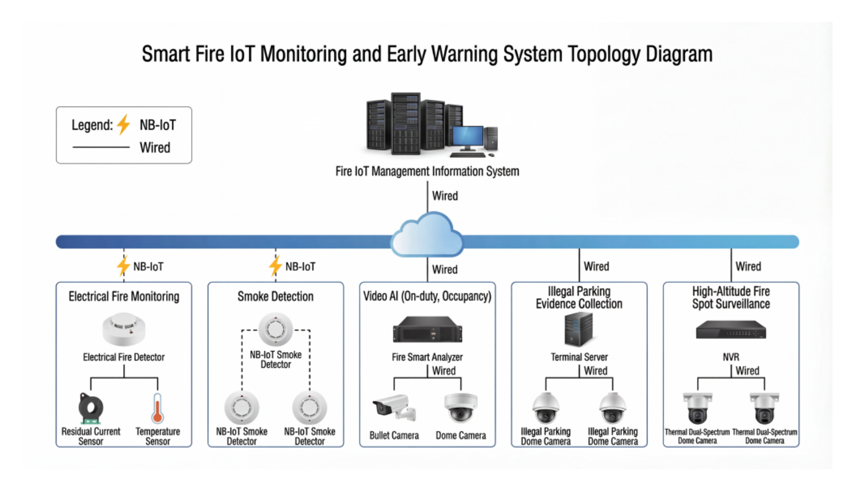
This fire-monitoring topology diagram template shows how sensors, monitoring components, and communication structure may be organized across an IoT environment. It helps users explain how the monitoring system works rather than reducing it to a generic list of connected devices.
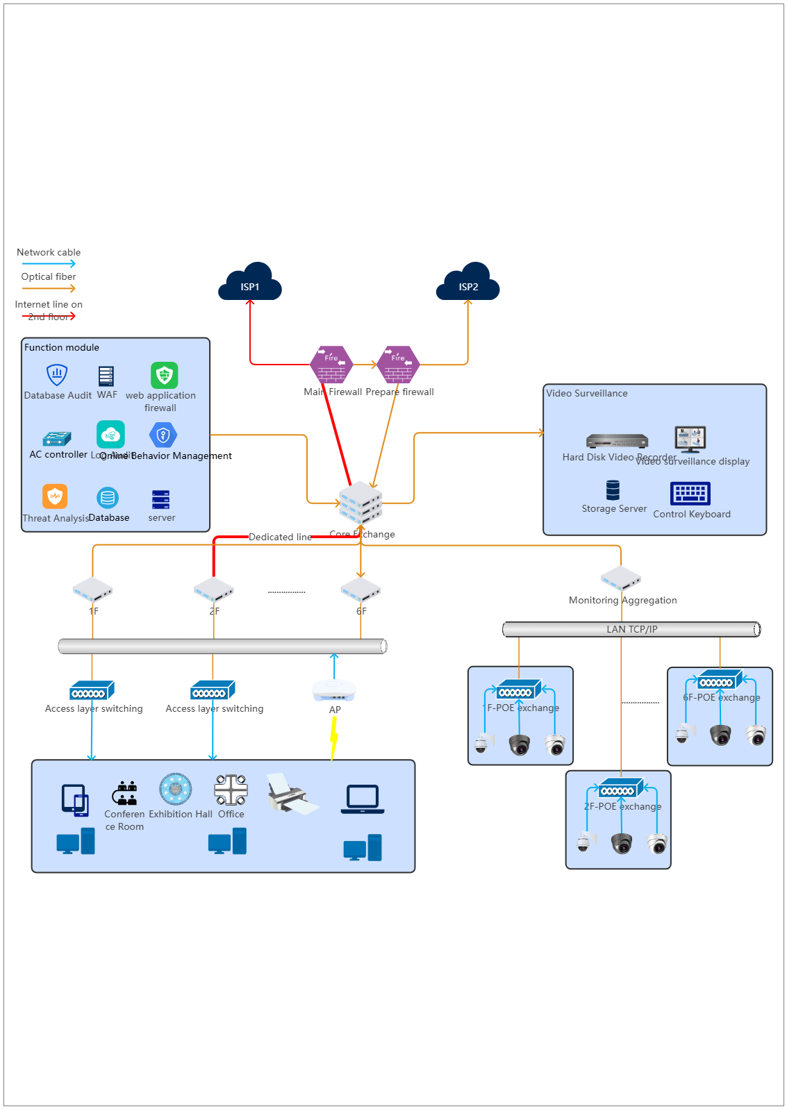
Monitoring-system components
The diagram appears to highlight the major technical elements that define the fire-monitoring environment. This matters because IoT monitoring review often depends on understanding which components play the key sensing, alerting, and system-support roles.
- Helps explain the major elements of the monitoring system
- Supports technical planning and documentation
- Useful for clearer system communication
Sensor and alert relationships
The visual arrangement also helps users review how sensors, alerts, and monitoring-related parts connect instead of treating them as isolated blocks. In a safety-monitoring topology, these relationships matter because the value of the system depends on how clearly the communication structure is organized.
- Shows how monitoring parts may relate across the topology
- Supports discussion of communication and dependency logic
- Useful for explaining system flow more clearly
Operational and safety-review value
Beyond the devices themselves, the diagram helps users discuss how the monitoring environment may be reviewed, documented, or communicated across teams. This is useful because safety-related systems often depend on shared understanding as much as on hardware placement.
- Useful for review, explanation, and technical alignment
- Supports clearer safety-system communication
- Helps make the topology reusable as a reference
FAQs about this Template
-
What is a network diagram?
A network diagram is a visual map of devices, services, links, and communication paths inside a network environment. It helps teams understand how systems connect, where dependencies sit, and how the infrastructure is organized for design, review, troubleshooting, or documentation.
-
What should a network diagram include?
A network diagram should include the main devices, zones, services, and access paths relevant to the environment. Depending on scope, it may also show routers, switches, firewalls, servers, cloud links, security boundaries, or how internal and external systems interact.
-
What is the difference between a network diagram and a topology diagram?
A network diagram is a broad visual map of the environment, while a topology diagram focuses more specifically on how components are arranged and connected. A topology view emphasizes structure, while a general network diagram may also include more functional or operational detail.
-
Why is a network diagram important?
A network diagram is important because it improves communication, review, and troubleshooting before or during system changes. It helps teams document infrastructure clearly, explain dependencies faster, and reduce confusion across both technical and non-technical stakeholders.