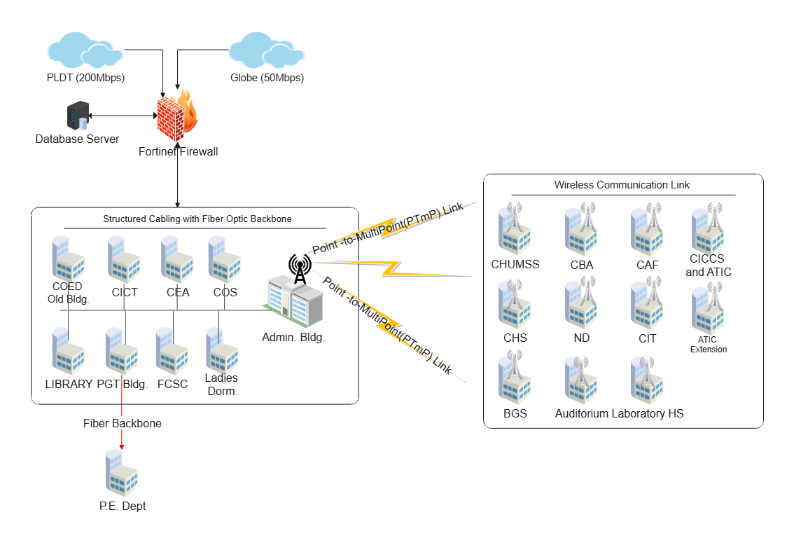
About Fiber Optic Logical Network Diagram Template
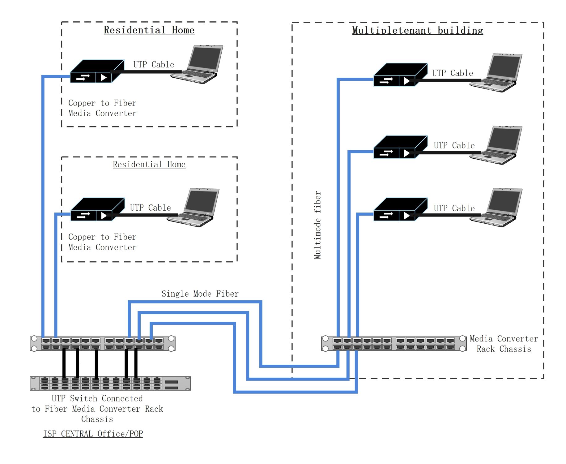
This fiber-optic network diagram template shows how network segments, optical links, and logical relationships may be organized across one environment. It helps users explain the structure more clearly than a generic list of network components and paths.
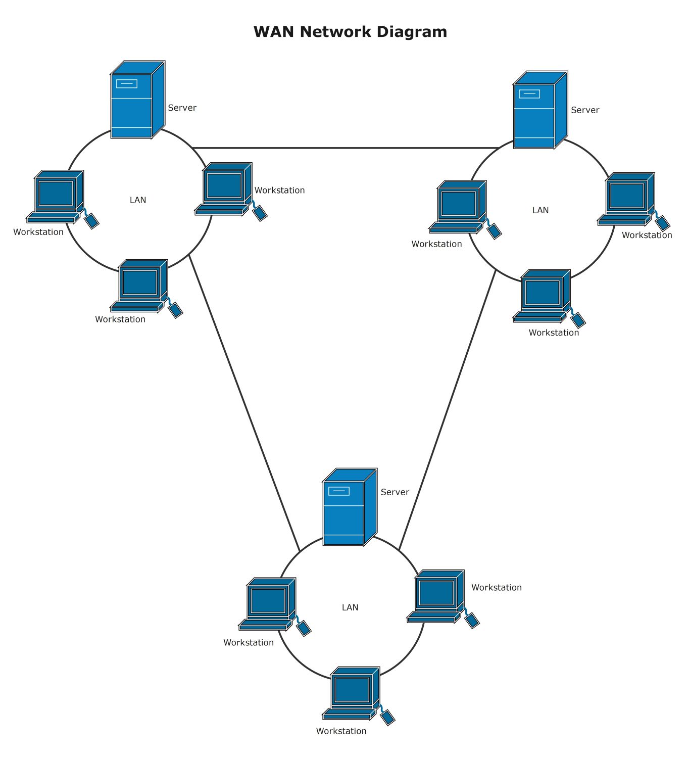
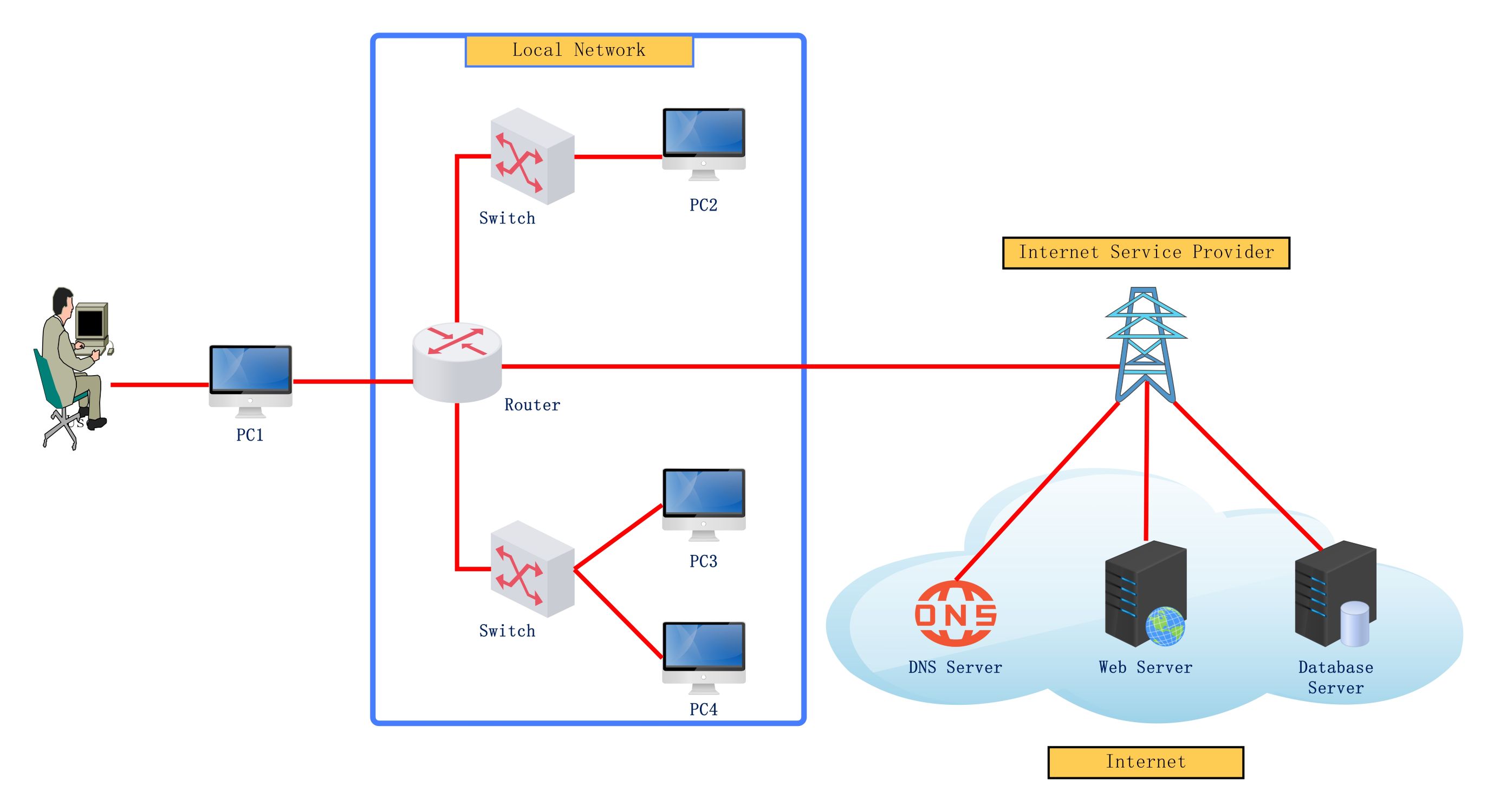
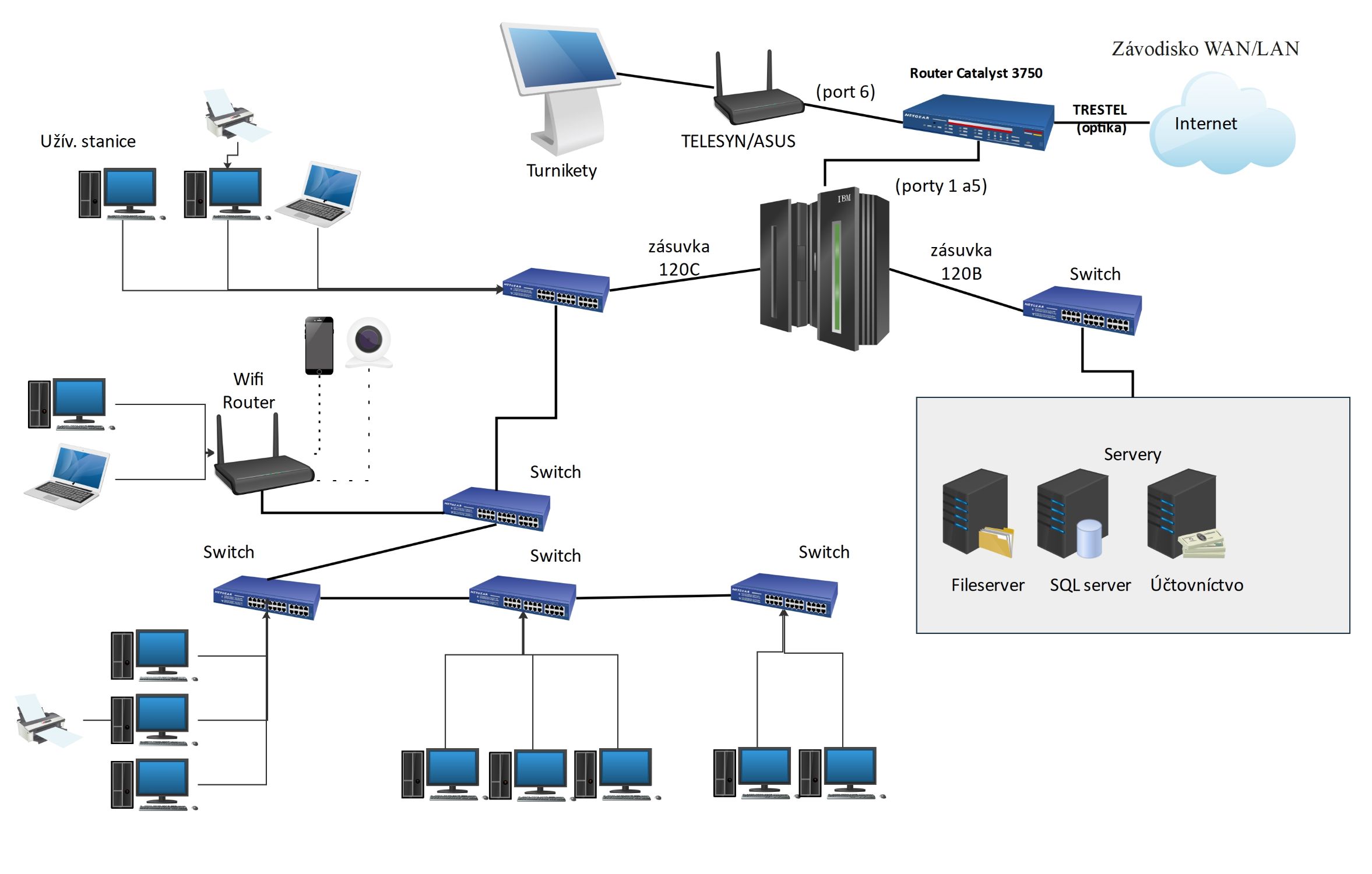
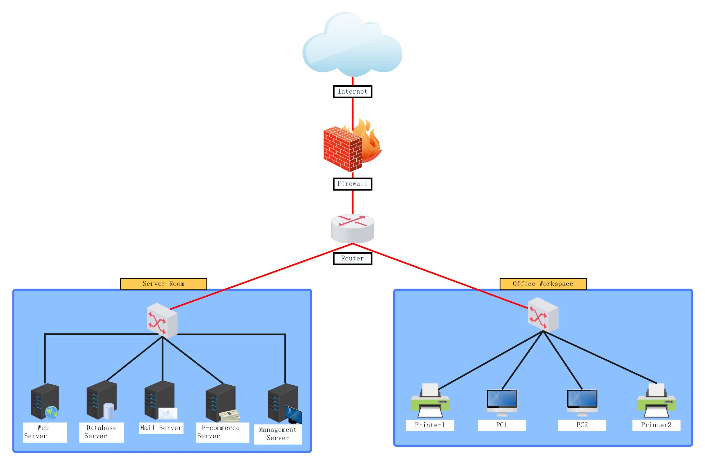
Network segments and core components
The diagram appears to highlight the major network sections or technical elements that define the environment. This matters because logical-network review often starts with understanding which segments and components carry the main structural roles.
- Helps explain the main sections of the optical network environment
- Supports technical planning and documentation
- Useful for clearer infrastructure communication
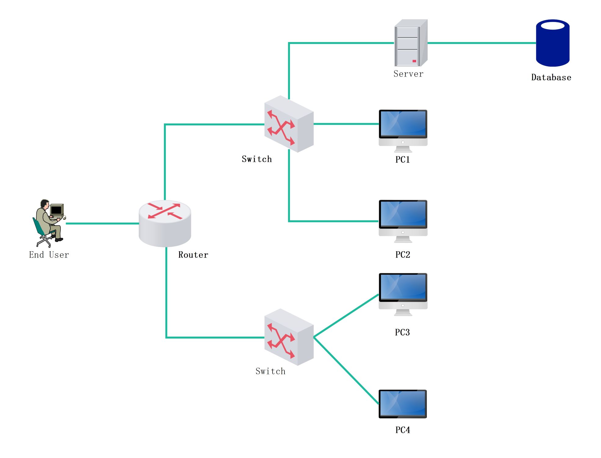
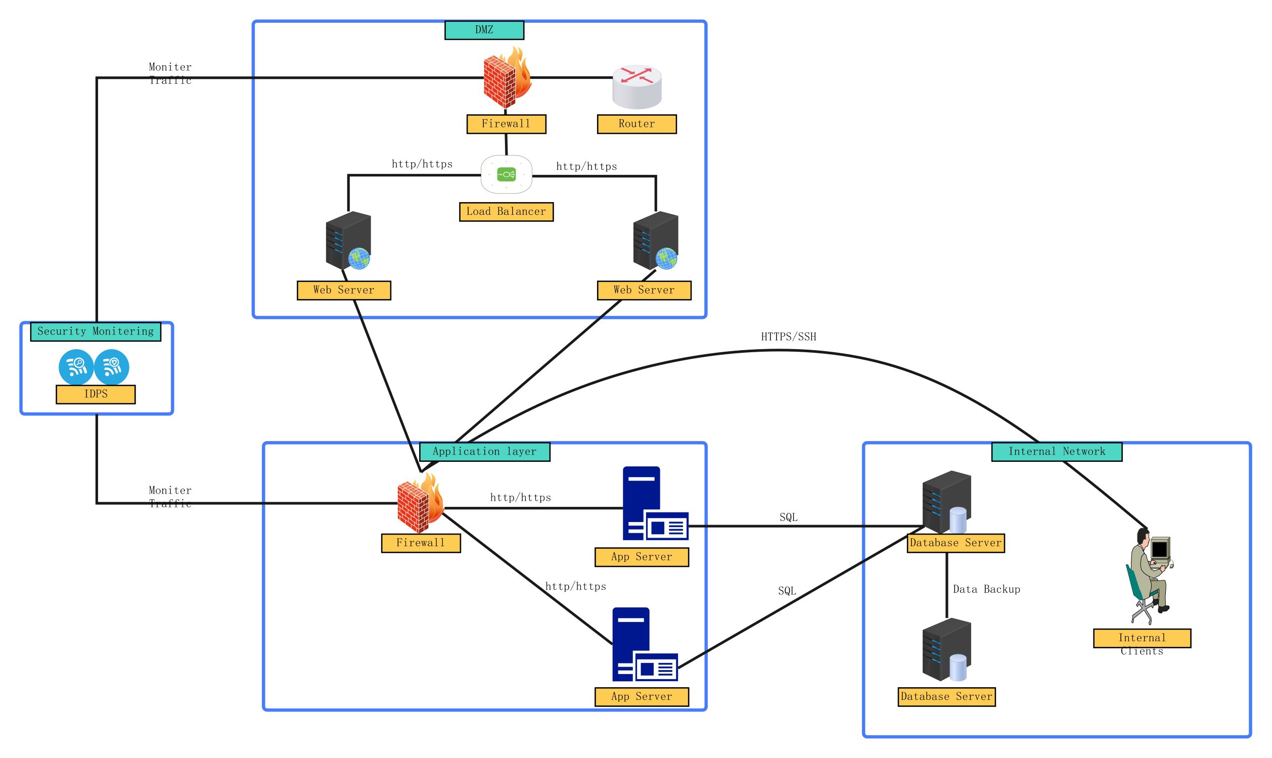
Optical links and logical relationships
The visual arrangement also helps users review how the components and segments connect rather than treating them as isolated labels. In a logical network diagram, these relationships matter because the network is usually understood through connection logic more than physical placement alone.
- Shows how optical links shape the network structure
- Supports discussion of communication and dependency logic
- Useful for explaining the environment more clearly
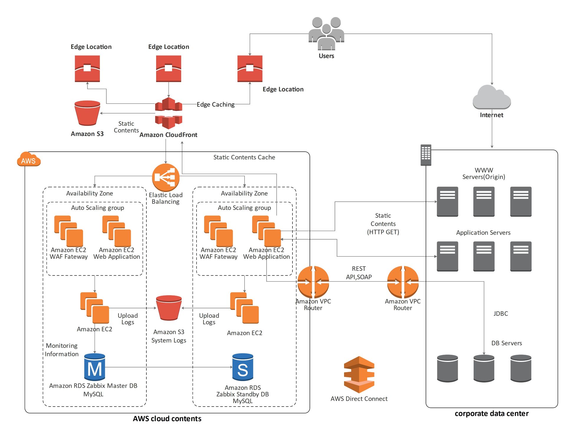
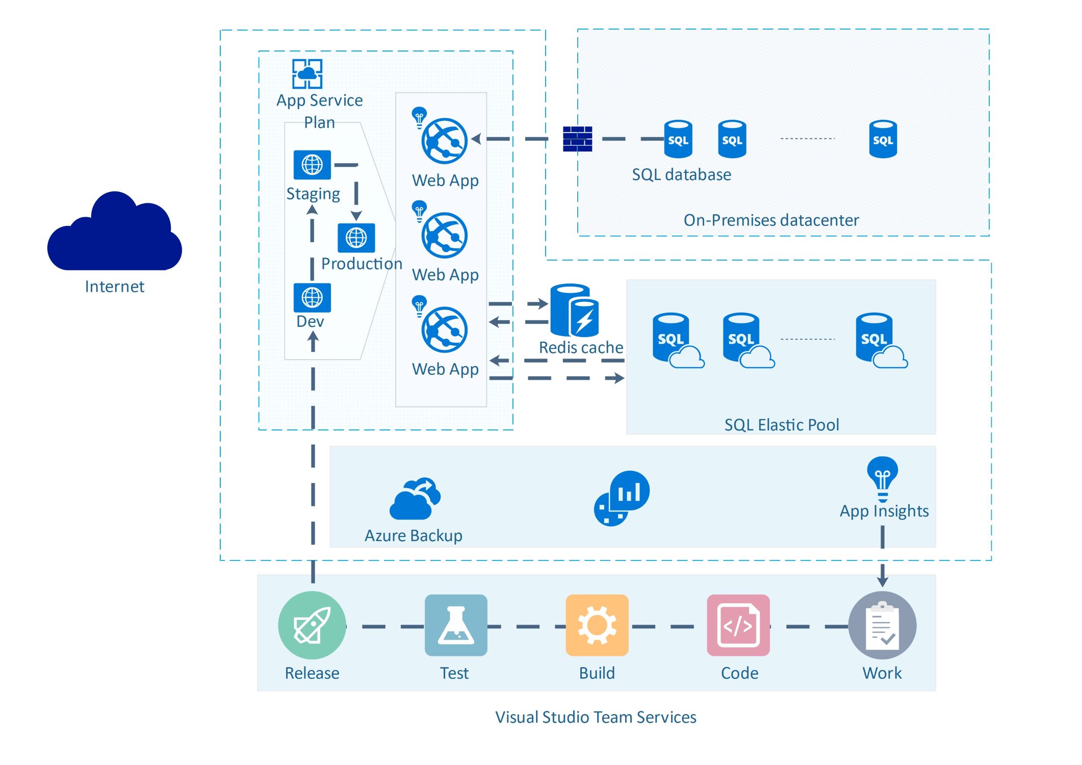
Review and architecture value
Beyond the links themselves, the diagram helps users create a reusable technical reference for review, documentation, and planning. This is useful because optical-network diagrams often need to support both long-term architecture understanding and day-to-day technical explanation.
- Useful for documentation, review, and technical explanation
- Supports clearer communication around logical network structure
- Helps make the diagram easier to reuse as a reference
FAQs about this Template
-
What is a network diagram?
A network diagram is a visual map of devices, services, links, and communication paths inside a network environment. It helps teams understand how systems connect, where dependencies sit, and how the infrastructure is organized for design, review, troubleshooting, or documentation.
-
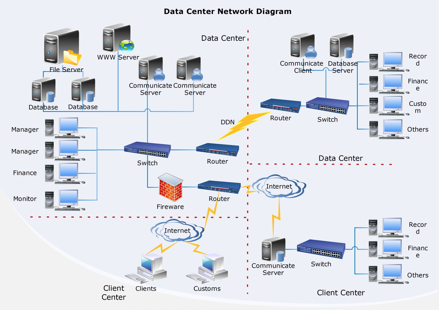
What should a network diagram include?
A network diagram should include the main devices, zones, services, and access paths relevant to the environment. Depending on scope, it may also show routers, switches, firewalls, servers, cloud links, security boundaries, or how internal and external systems interact.
-
What is the difference between a network diagram and a topology diagram?
A network diagram is a broad visual map of the environment, while a topology diagram focuses more specifically on how components are arranged and connected. A topology view emphasizes structure, while a general network diagram may also include more functional or operational detail.
-
Why is a network diagram important?
A network diagram is important because it improves communication, review, and troubleshooting before or during system changes. It helps teams document infrastructure clearly, explain dependencies faster, and reduce confusion across both technical and non-technical stakeholders.