Ford tractor alternator wiring diagram
Transform your Ford tractor with our easy alternator wiring diagram for seamless power!
- Templates
- Wiring diagram templates
- Ford tractor alternator wiring diagram
About this Ford tractor alternator wiring diagram
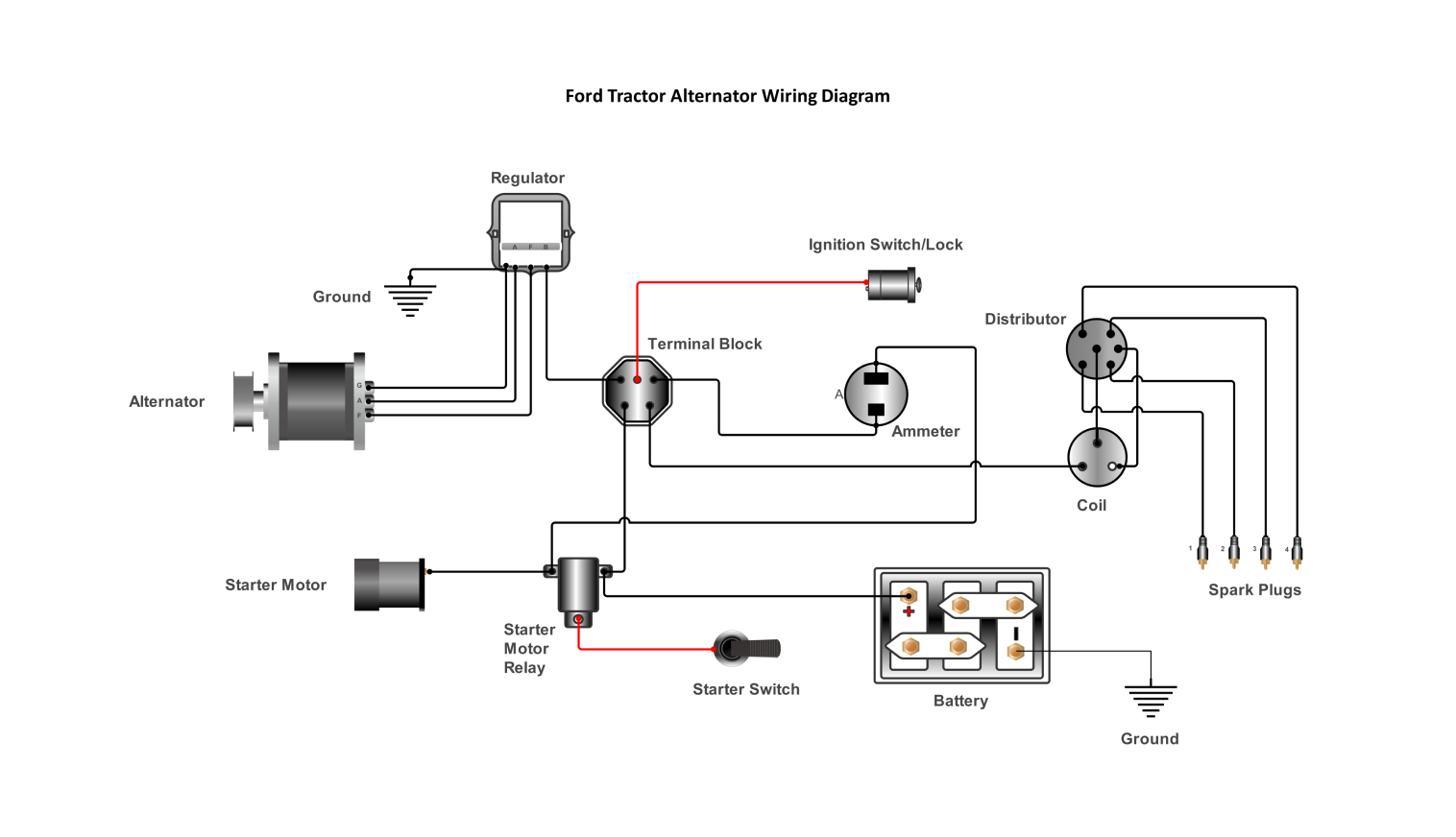
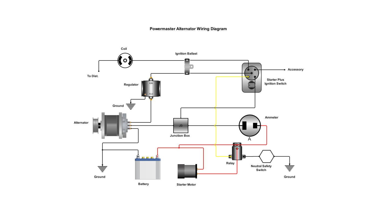
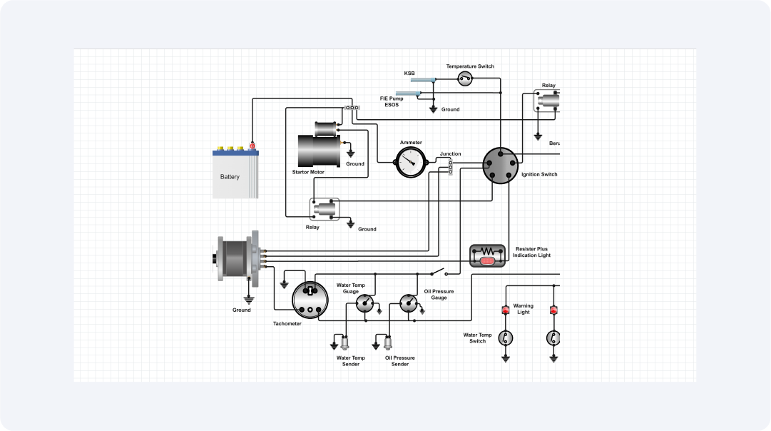
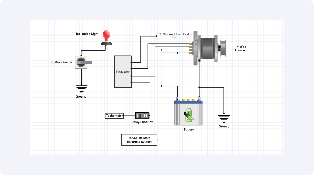
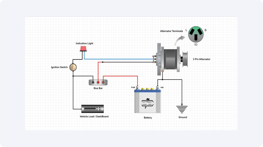
This template gives a complete overview of the wiring diagram for a Ford tractor alternator, comprising three critical terminals and their connections to enable efficient functioning and reliable charging of the tractor's electrical system.
The G (Ground) terminal connects the alternator to the tractor's chassis, establishing a necessary ground connection. Proper grounding is important for the alternator's efficient working, and the diagram clearly depicts the correct grounding method.
A (Alternator Output) terminal is the principal output, connecting the alternator to the voltage regulator. The diagram illustrates how to wire this terminal to the regulator to facilitate effective power transfer and charging.
The F (Field) terminal connects to the voltage regulator, which controls the alternator's output by regulating the current in the field windings. The diagram gives explicit directions for wiring this connection to the regulator to guarantee reliable voltage regulation.
The diagram illustrates the connection from the alternator's output to the regulator. The regulator then connects to the battery and other components. This configuration guarantees that the alternator's output is correctly regulated and distributed, giving consistent charging and power supply to the tractor's electrical system.
This user-friendly template has properly wired and labelled components, making it perfect for both professional technicians and DIY enthusiasts. It serves as a crucial instruction for effectively installing or repairing a Ford tractor alternator.
By following the schematic, users may guarantee the alternator and regulator operate together properly to maintain reliable charging and support the tractor's electrical system.
Related templates


Get started with EdrawMax today
Create 210 types of diagrams online for free.
Free Download Free Download Draw a diagram free Draw a diagram free Draw a diagram free