GM 1 wire alternator wiring diagram
Simplify installation with our GM 1 wire alternator wiring diagram for optimal performance.
- Templates
- Wiring diagram templates
- GM 1 wire alternator wiring diagram
About this GM 1 wire alternator wiring diagram
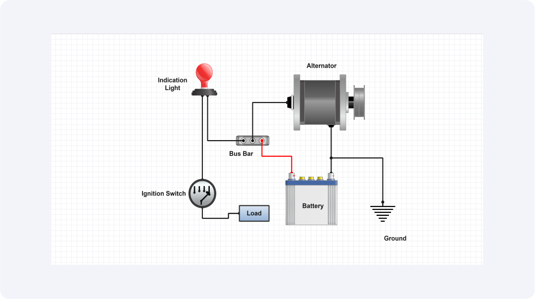
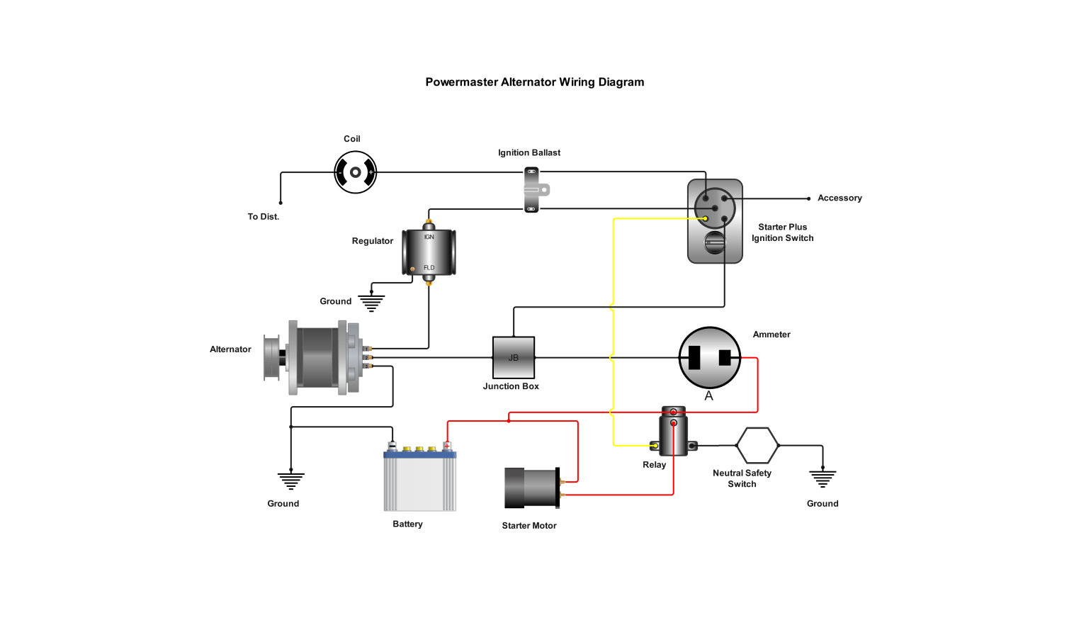
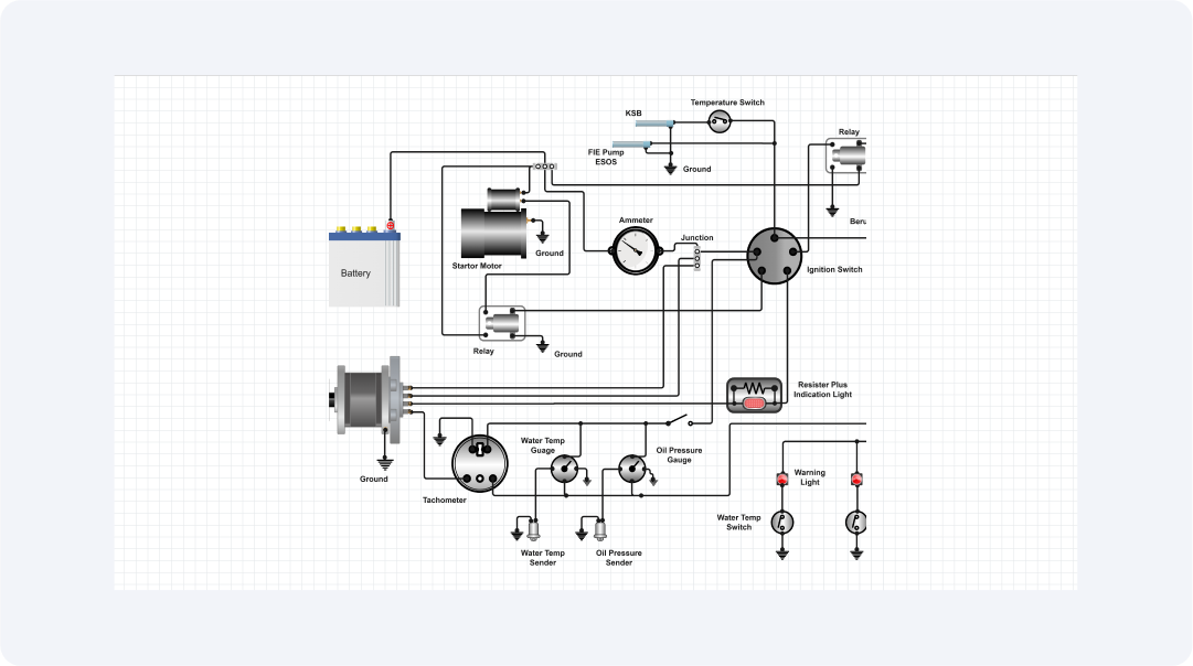
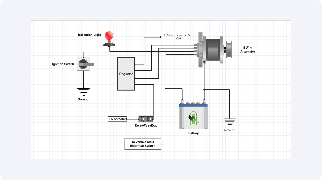
This template for a 1-wire alternator wiring diagram gives a thorough and understandable representation of the necessary parts and connections for installing a 1-wire alternator in a car. Developed for both novice and expert mechanics, this template makes replacing or upgrading the charging system in your car easier.
The efficiency and simplicity of a 1-wire alternator are its main attractions. A 1-wire alternator connects to the battery with just one wire since it integrates the voltage regulator inside, unlike conventional alternators that need several connections. This makes the engine bay cleaner, lessens possible places of failure, and simplifies wiring.
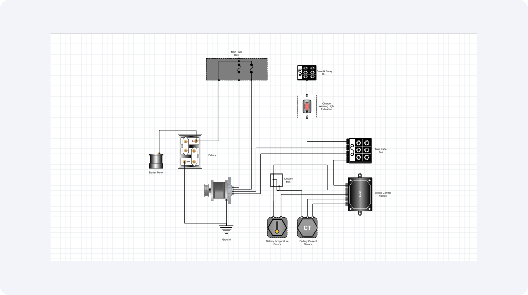
The main electrical power producing component is called an alternator. An engine starts and the electrical systems of the car are powered by the energy stored in the battery.
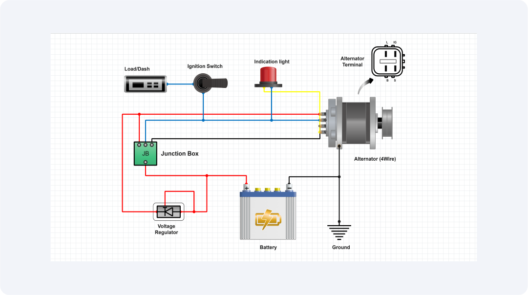
Reliable and steady grounding to the chassis of the car is guaranteed via Ground Connection. One wire is the primary wire that connects the alternator to the battery or starting solenoid.
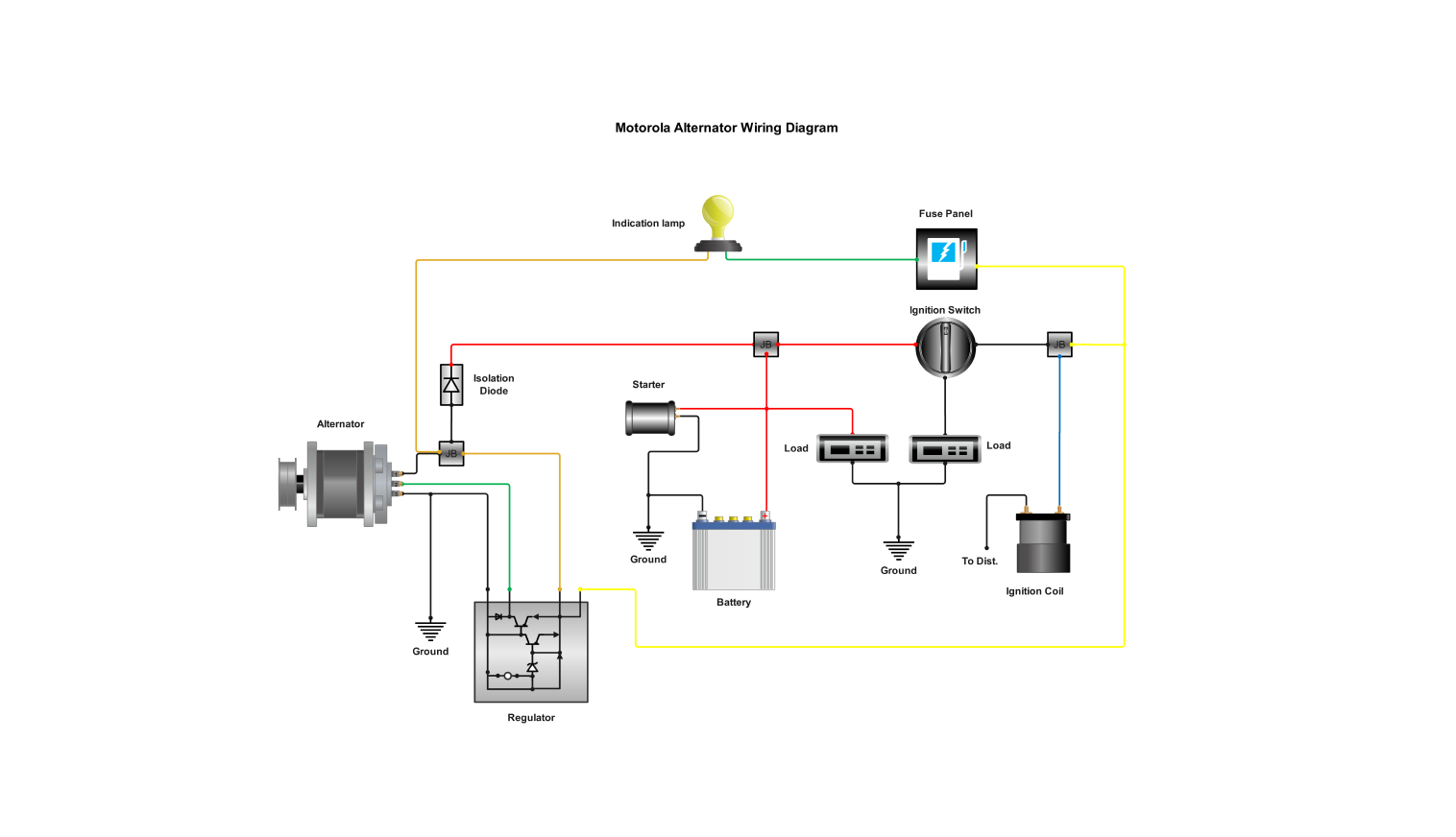
Using suitable brackets, fasten the alternator and make sure it lines up with the engine's pulley system. Attach the single wire to the alternator's output terminal. This wire normally connects straight to a junction block or starter solenoid or the positive terminal of the battery.
Bolt the alternator to the engine block, which is grounded to the chassis, to guarantee a strong ground connection. Use of an extra grounding strap might increase dependability. Starting the engine, check the output of the charging system with a voltmeter; it should be between 13.8 and 14.5 volts.
Related templates


Get started with EdrawMax today
Create 210 types of diagrams online for free.
Free Download Free Download Draw a diagram free Draw a diagram free Draw a diagram free