Perkinson alternator wiring diagram
Effortlessly connect your Perkinson alternator with our simple and clear wiring diagram.
- Templates
- Wiring diagram templates
- Perkinson alternator wiring diagram
About this Perkinson alternator wiring diagram
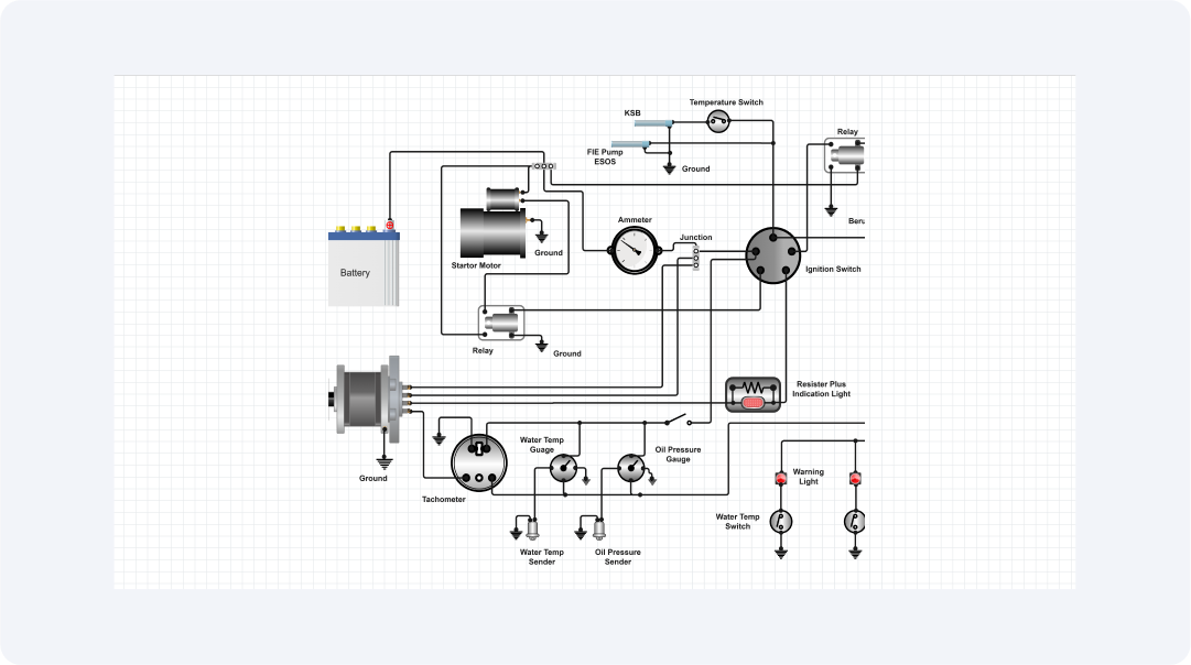
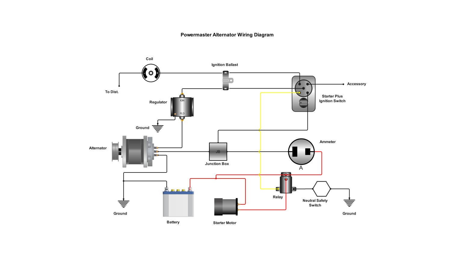
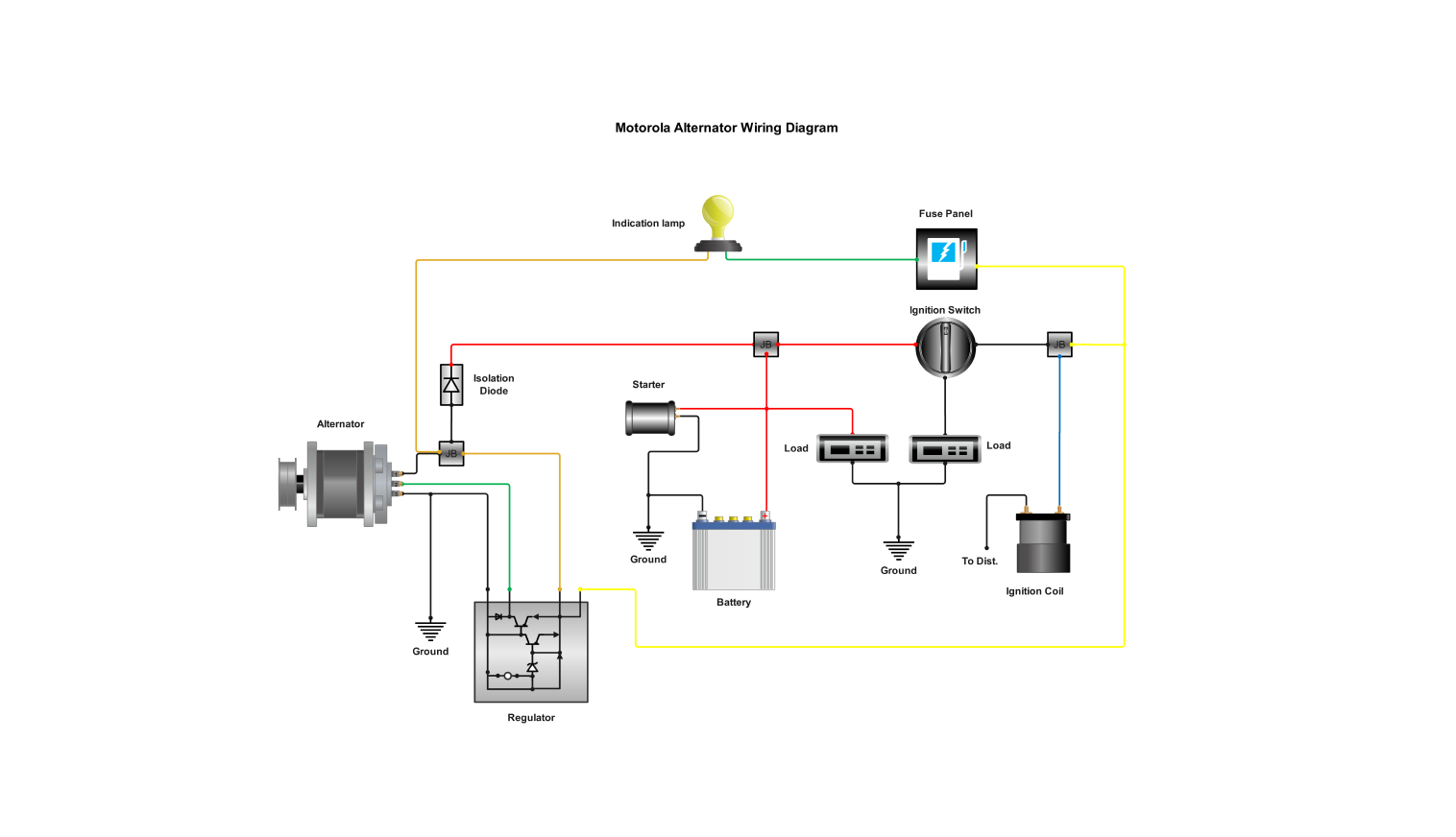
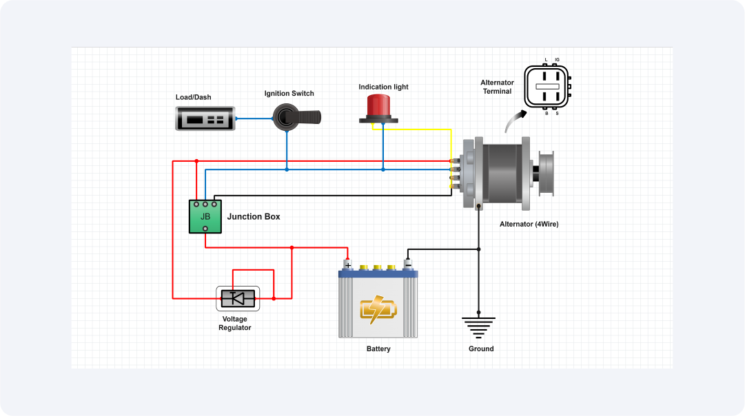
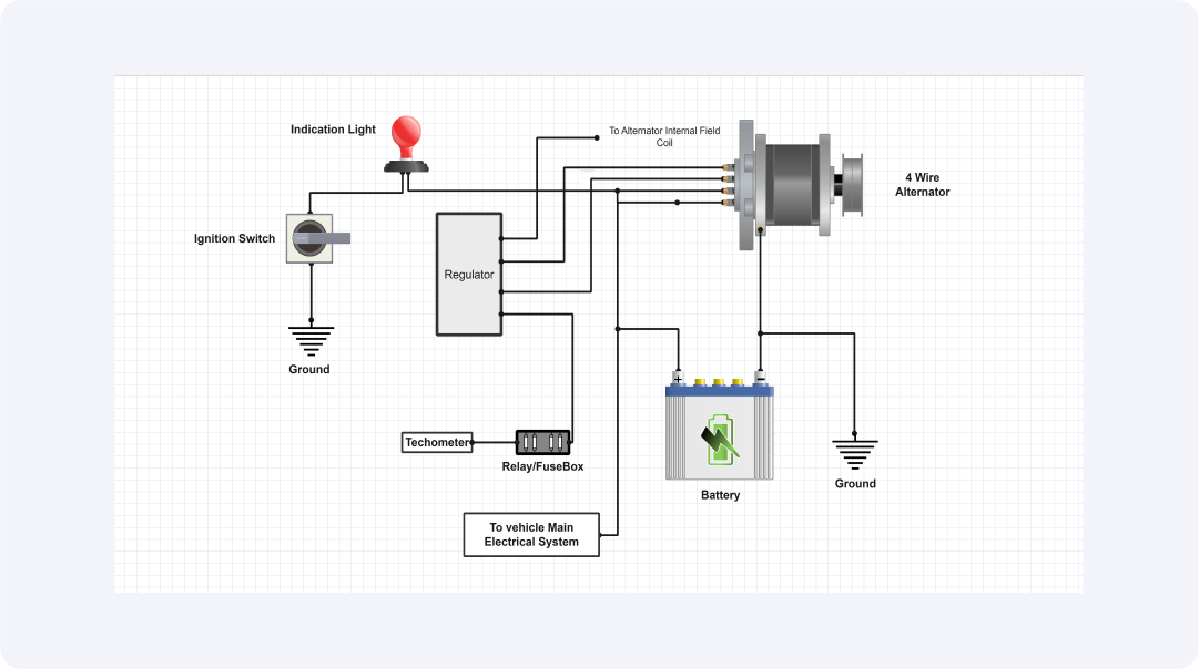
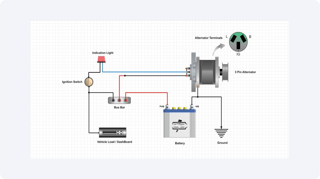
This Perkinson alternator wiring diagram template is designed to provide a clear and detailed guide for properly wiring a Perkinson alternator into older vehicle systems. The alternator features four essential terminals: F (Field), R (Relay/Regulator), L (Lamp), and S (Sense), each of which plays a vital role in ensuring reliable electrical system performance. Whether you are a professional mechanic or an automotive devotee, this template helps you install the alternator with accuracy and simplicity.
The field terminal (F) monitors the output of the alternator by adjusting the magnetic field. It connects to the regulator (internal or external) of the alternator, which controls the voltage provided to the battery.
The relay or regulator terminal (R) connects to a voltage regulator or relay, controlling the alternator's voltage outputs to maintain steady battery charging without overcharging or undercharging the system.
The Light or Indication terminal (L) relates to the dashboard warning light. If the charging system faces an issue, such as a malfunction or low power, the warning light will glow, telling the driver to inspect the system.
The sense terminal (S) normally connects to the tachometer, as well as other gauges and sensors, to monitor engine RPMs and offer real-time input. This connection enables the alternator to regulate its output based on engine speed and electrical demand, ensuring the system runs efficiently.
By following this diagram, users can accurately integrate a Perkinson alternator into a vehicle’s electrical system, ensuring optimal performance and efficiency. This template is ideal for professionals, technicians, and aficionados working with vintage automobiles, offering precise instructions for effective installation.
Related templates


Get started with EdrawMax today
Create 210 types of diagrams online for free.
Free Download Free Download Draw a diagram free Draw a diagram free Draw a diagram free