


Modeling state transitions in UML is a prerequisite for software design and it’s no less than climbing a mountain. Popularly known as a transition or state diagram, a state machine diagram helps administrators streamline processes by identifying and reducing bottlenecks. However, maintaining the transition’s flow, accuracy, and intricacy in a state diagram intimidates many.
Enters MS Visio with a versatile and professional interface! Most professional setups accept Visio as a go-to choice for modeling state transitions. That said, smart and intuitive state machine diagram generators like EdrawMax might work better for newbies entering the corporate world. Here is how to draw a state machine diagram in Visio and EdrawMax for deciding on a convenient option.
In this article
How to Create a State Machine Diagram in Visio
MS Visio has become a staple choice for creating state machine diagrams, thanks to its drag-and-drop functionality and extensive shape library. Here are the key steps to prepare organized and accurate Visio state machine diagrams from scratch.
- Install Visio and click the File tab from the dashboard. Click New > Software and Database from the categories menu for a suitable template.
- Scroll down to find the UML State Machine Diagram, select US Units or Metric Units, and click Create.
- Once on the editing panel, go to the Design tab and change Orientation > Landscape. This orientation will help with the diagram’s flow.
- It is time to draw states. Go to the left-side panel of the diagram and drag shapes to the canvas. Create a rough outline for the diagram’s state.
- If you do not see a Shapes window next to your diagram, navigate to View > Task Panes and select Shapes. Press Expand the Shapes button on the left and drag them onto the canvas.
- Double-click any shape to insert the text. Change the appearance or font of the shape from the Home tab.
- The next step is building connections. Just like shapes, connectors are located on the left window of the diagram. Drag them to link the shapes together. Add trigger actions and guard conditions by double-clicking the connector points for better system behavior clarity at each step.
- Select the check box next to Connection Points on the View tab if connectors are not visible.
- Finally, the state machine diagram is complete. You can return to individual elements and modify their color or font from the Home tab.
- Once satisfied, download the diagram. Navigate to the File menu and click Save As > This PC > Desired Location.
Making a UML state transition diagram requires intricacy, analysis, and advanced editing features. Though Visio has a sufficient toolkit, it may not be seamless for creating transitions. The overlapping states, inadequate transition building, and connector alignment are big issues with Visio. Plus it is not free. So, it may turn even a simple state transition diagram creation into an extensive hours-long process.
How to Create a State Machine Diagram in EdrawMax
What if there is a quick way to create a similar state machine diagram; sound convenient?
In addition to a user-friendly interface and a symbol library, EdrawMax has numerous easy-to-customize user-generated state machine diagram templates. It saves time and effort, helping you with tight deadlines. Let’s see how it goes.
Before you begin, download, install, and launch the EdrawMax desktop version. Log into the Wondershare ID or access the software using your social media accounts (Facebook, Google, etc).
Step 1
Visit the Templates section from the dashboard and type State Machine Diagram in the search box. Scroll down to find the right fit for your task. Once decided, click Use Immediately to duplicate.

Step 2
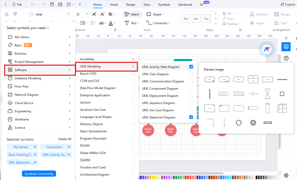
Once on the editing panel, import the state machine diagram symbols. Navigate to the left side of the canvas and click More Symbols > Software > UML Modeling > Activity State.
Step 3
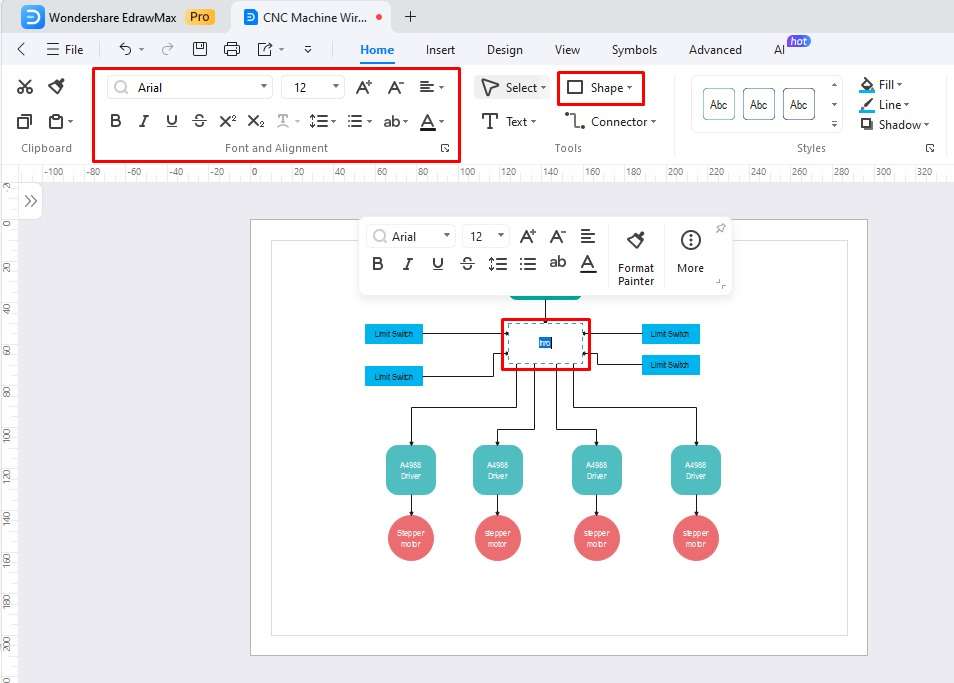
Drag desired symbols on the canvas to create states, initial, and exit points. Double-click any shape to insert text. Change the font style and replace the shape from the Home tab.
Step 4
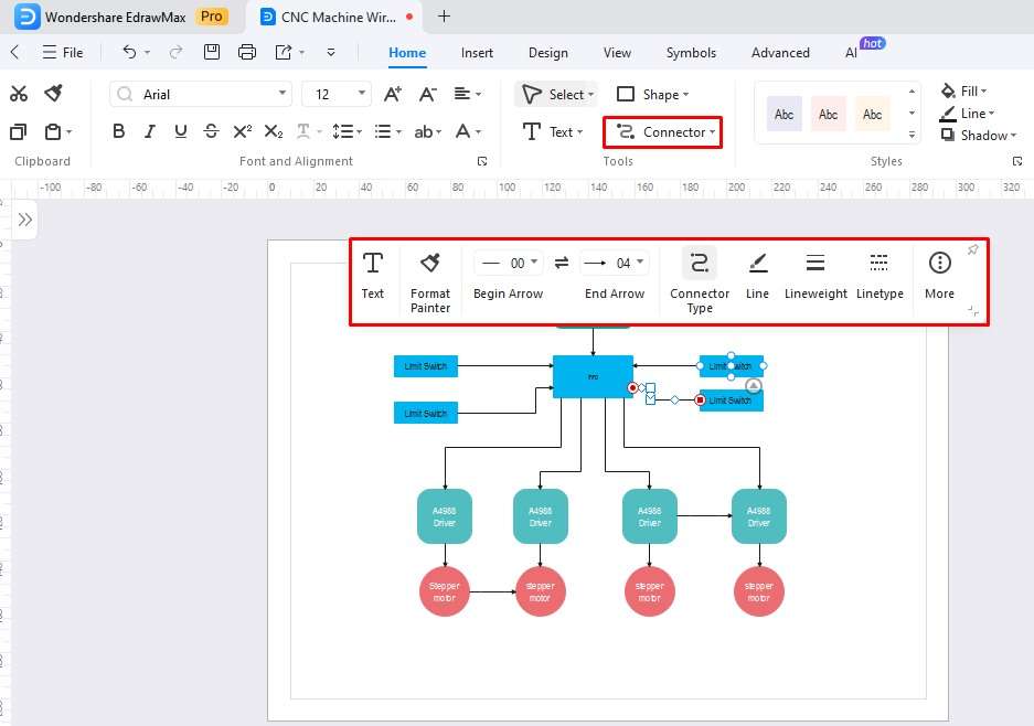
It’s time to build connections. Click Connector from the Home tab and join any two elements in the system structure. You can adjust the thickness, arrow shape, and line type from the on-screen prompt.
Step 5
Now, add the trigger events and guard conditions. Just double-click anywhere on the connector and add descriptive labels.
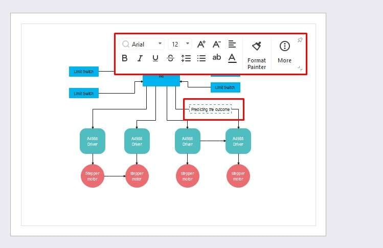
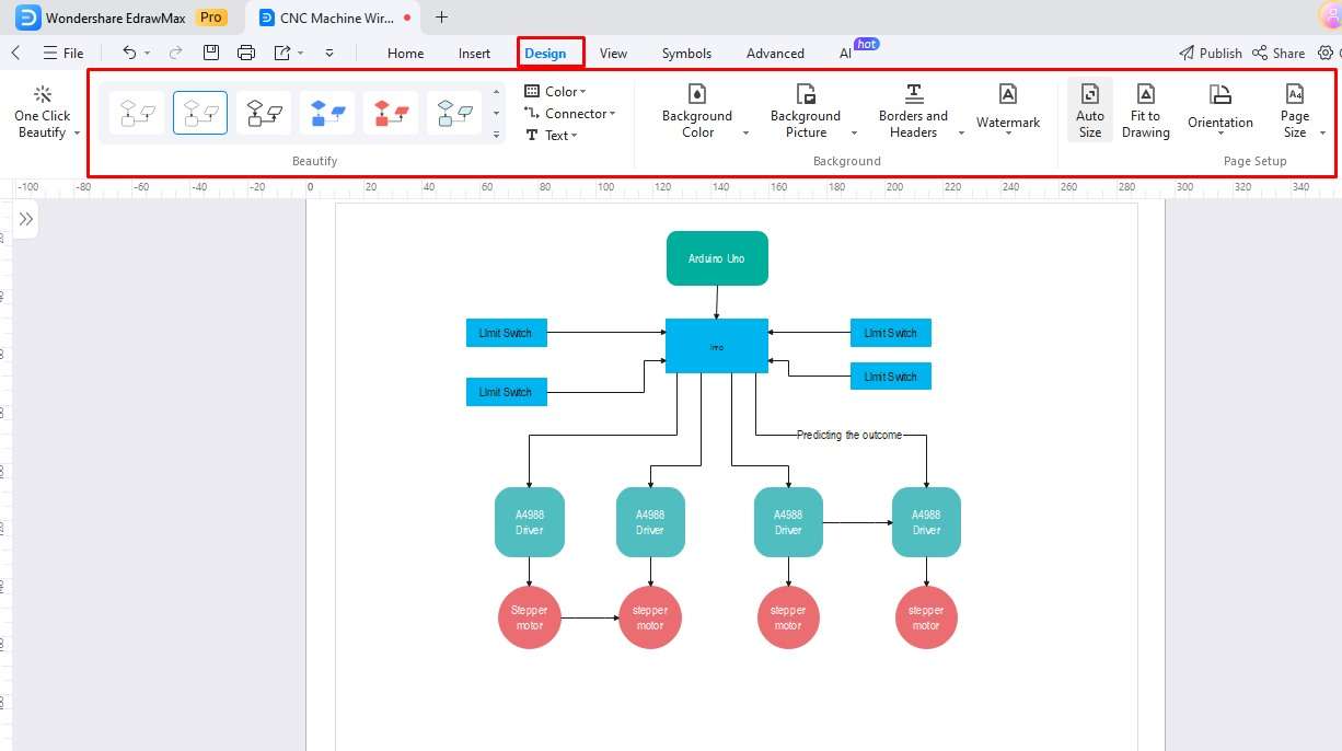
Step 6
We are almost there. Just modify the diagram appearance by navigating to the Design tab from the top. It allows changing the state’s color, theme, orientation, and background image.
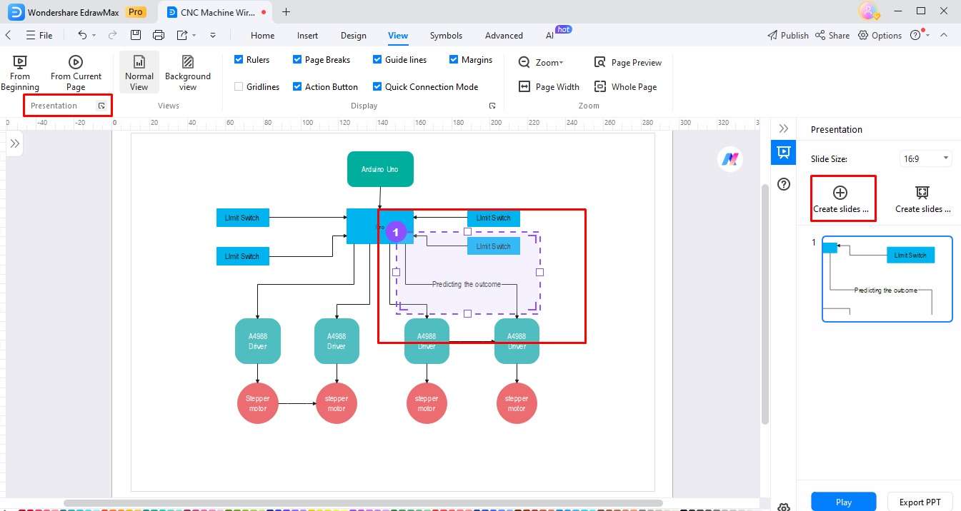
Step 7
Congratulations, the UML state machine diaphragm is ready. Now, you can even present it from EdrawMax. Enable the Presentation Mode from the View tab and select square areas of the diagram to make an extensive slideshow. Press F5 to enter the full-screen display.
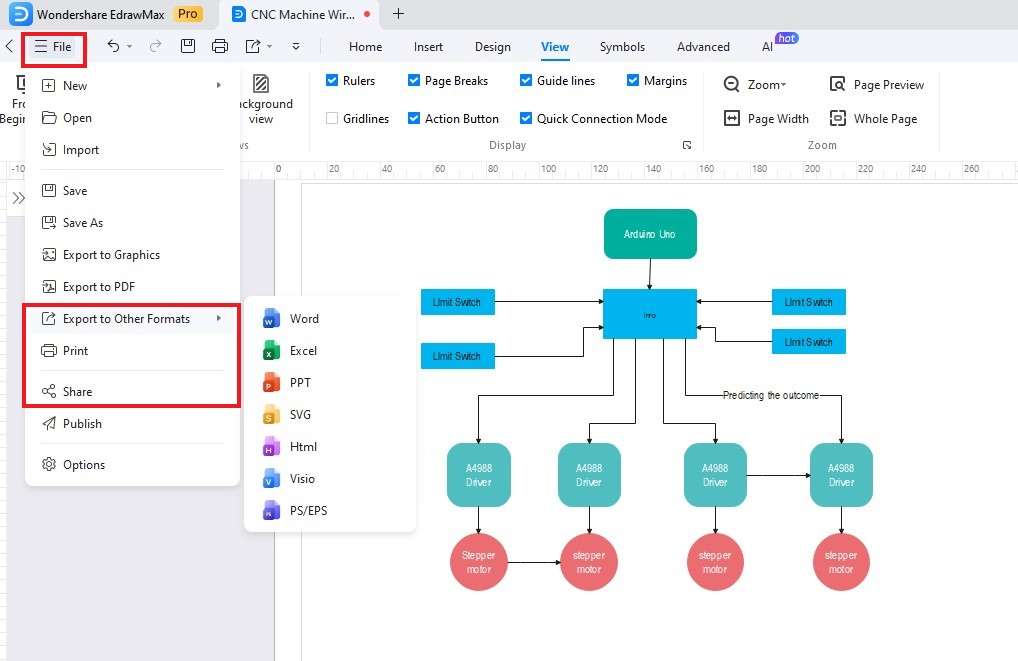
Step 8
Finally, export your diagram. Navigate to the File menu and select a preferred format (PNG, PDF, JPG, Visio, etc). Or, share it with social media friends.
What is Wondershare EdrawMax?
EdrawMax is an advanced diagramming tool with a UML diagram maker. Its premade templates and extensive symbol library are an all-in-one UML modeling solution. What’s even better is its AI collection of tools that assist you in research, diagramming, and presentation, simplifying routine organizational tasks. Let’s see why it is a better Visio substitute for corporate officials.
Key Features
- Symbol Library: You can find readily available states, connectors, or transitions from the EdrawMax symbol library. It features over 26,000+ vector symbols, including UML and software design. Create a personalized UML symbol inventory and drag them onto the canvas.
- Massive Template Community: EdrawMax has state transition diagrams for software engineers, project managers, database designers, and system analysts. You can personalize them or get creative inspiration from them. Visit the community and find an easy-to-customize state diagram to kickstart your state transition modeling in UML.
- Multi-Format Export: No longer format conflicts with EdrawMax. It supports over 10+ export formats, including Visio, PDF, and PNG. Not only this, but it further allows importing unfinished projects from Visio, SVG, and CAD.
- Cross-Platform Support: With EdrawMax, you can access projects from anywhere, anytime. This software is compatible with Linux, Windows, Android, MacOS, and iOS. Plus, it even has an online version that works on any device with the internet.

Reasons to Choose
- Cost Effective: EdrawMax has flexible pricing plans for students, teams, and businesses, in addition to a free version. The free plan covers essential editing tools, user-generated templates, and symbols. You can find more about subscriptions on the pricing page.
- Productive and Efficient: EdrawMax’s free templates and AI assistance help administrators streamline projects effectively. Moreover, it has a revision history function, allowing you to track project modifications.
- Beginner Friendly: No advanced design skills are needed to use EdrawMax! This platform has an intuitive interface with drag-and-drop functionality and an accessible toolkit. You can also find documented user guides and video tutorials on the official website.
Tips for Creating a State Machine Diagram
A UML state machine diagram is a powerful visualization tool for understanding a system’s behavior. However, making them can be intimidating, as you can easily end up with cluttered and confusing outcomes. Here are some tips that may help the organization and accuracy of the flow of state machine diagrams.
- Implement consistent shapes and colors for each state category to bring clarity. For instance, green rectangles for normal states and blue circles for initial and final states can help bring organization.
- Always dedicate descriptive names to each state and connector points. Adding labels for transitions aids in better visualization of complex systems in minutes. Moreover, action triggers and guard conditions in state transitions are the viewer’s roadmap to predict the next step.
- Most people underestimate this, but layering can introduce accuracy and intricacy in state machine diagrams. EdrawMax and Visio both have sub-machine diagram shapes to incorporate compound states. So, use them to create detailed and clear system behavior patterns.
Conclusion
Visio state machine diagrams have become a staple in the professional world. Similarly, EdrawMax proves to be useful for many diagram types. All thanks to their drag-and-drop functionality, Visio and EdrawMax might become a game changer for state machine diagrams. However, make sure you buy Visio to make such complex diagrams. Unfortunately, it is not a free tool like EdrawMax.
