Frequency divider symbols
Get a clear picture of common frequency divider symbols to make accurate measurements.
- Templates
- Circuit diagram templates
- Frequency divider symbols
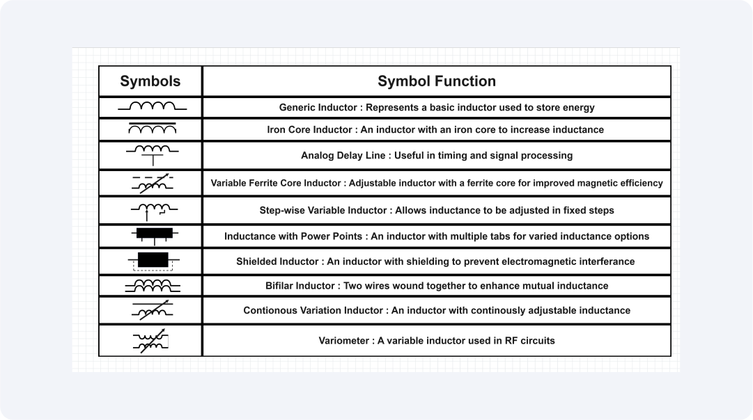
About these frequency divider symbols
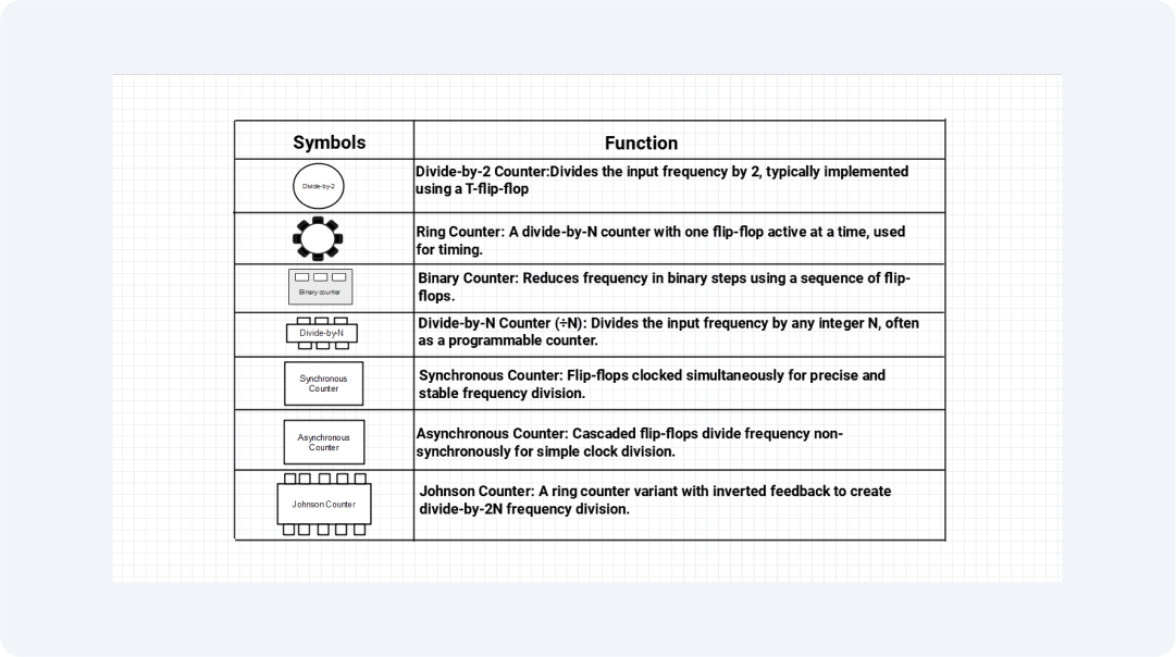
These frequency divider symbols find common application in the design of digital circuits as helping to visually distinguish between various types of counters it also details their specific purpose.
The basic example of a synchronous counter is a divide-by-2 counter which is produced using a T-flip-flop, the state of which changes on each clock transition therefore halving the input to the flip-flop frequency. Ring counters for example have half simple flip-flops and are unique in the fact that only one flip-flop is active at any one time.
This characteristic makes them well suited for timing application since they produce a cycle and predictably too. Binary counters, on the other hand, employ a flip-flop chain to divide the high frequency into binary stages. Its capacity to represent frequency division in powers of two puts the binary number at the center of the construction of digital systems.
Divide-by-N counters add a level of flexibility due to the ability to divide a frequency by any integer value of N. These counters are typically programmable to ensure the designers attain differentiated division frequencies that may be desirable.
Another considerable kind of synchronous counters is well-known for their high-precision and stable values. In these counters, all flip-flops are clocked on the same clock; this reduces the propagation delay and enhances the timing of output.
Asynchronous counters, also known as ripple counters; use a cascaded structure that uses the output of one flip-flop as the clock input to the other. As they are less complex in structure, they are much more vulnerable to propagate delays that restrict their performance in high-speed circuits.
Lastly, Johnson counters, a mutated form of ring counters uses inverted feedback to produce a sequence. These counters provide a division-by 2N of the frequency and are prized through flip flops for expected waveforms. Therefore, counters’ designers need to start with an understanding of the symbols and functions of these counters so that these circuits can be made to divide frequency tailored for some specific digital system.
Let's take a look at a few important frequency divider symbols:
Divide-by-2 counter
This symbol divides the input frequency by two and displays it in the T-flip flop inverting state for each clock pulse. It in its simplest form represents the division of frequency.
Ring counter
This symbol consists of dividing the input frequency by N where N is the number of flip-flops and the mechanism gives sequential and cyclic forms of output and is thus good for timing use.
Binary counter
This symbol subtracts the input frequency from a binary number by utilizing a device called a flip-flop which is useful in counting and producing binary numbers.
Divide-by-N counter
This symbol enables frequency division by integer N and provides easily selectable divisions from narrowband to wideband and everything in between, typically using dividers/counters.
Synchronous counter
This symbol splits the input frequency precisely with all the flip-flop counters synced, to provide timing stability to the outputs.
Asynchronous counter
In this symbol, smaller divisions of the input frequency are achieved by cascading flip-flops according to the sequential division technique.
Johnson counter
This symbol produces a divide-by-2N frequency division with inverted feedback that results in a simple sequence of outputs coherently.
Related templates
Get started with EdrawMax today
Create 210 types of diagrams online for free.
Free Download Free Download Draw a diagram free Draw a diagram free Draw a diagram free