Logic gate symbol
Understand common logic gate symbols to enhance your knowledge of digital circuits.
- Templates
- Circuit diagram templates
- Logic gate symbol
About the logic gate symbols
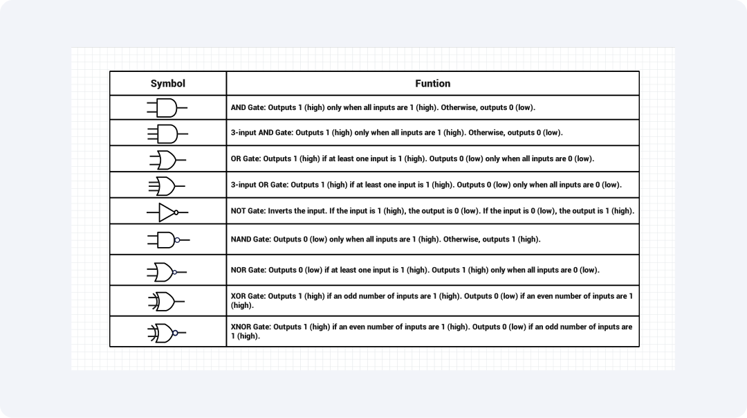
Logic gates are some of the basic components of digital electronics. They are components of different circuits. They perform calculations on binary data, which are 0s and 1s. These are specific logic gates, each with a particular purpose and operation.
These symbols have a certain standard. Knowing these symbols lets users read circuit diagrams. They can then design or repair digital circuits with great efficiency. Each logic gate performs a unique function depending on its binary inputs.
AND gate
The symbol for an AND gate is represented by a D-shape, with two inputs and one output. It is used in digital circuits where all conditions must be true to produce a HIGH output.
3-input AND gate
The symbol for a 3-input AND gate is represented by a D-shape, with three inputs and one output. Its functionality is similar to that of an AND gate, but the number of inputs has increased, making it more versatile.
OR gate
A symbol is represented by a curve featuring two inputs and a single output. It is frequently used in control systems in which an action results from a signal coming from one of several sensors, for example, temperature or pressure.
3-input OR gate
A symbol is represented by a curve featuring three inputs and a single output. It works the same as the OR gate providing more input options compared to a simple OR gate.
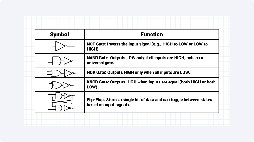
NOT gate
An arrow entering a symbol of a triangle points to a circle (inverter). It is used in signal negation and for controlling the devices in electrical circuits.
NAND gate
An AND gate symbol with a small circle (inverter) beside the output. It is complementary to the AND gate and is extensively used in memory cells because it has the property of AND and is also efficient in negation to conserve power.
NOR gate
An OR gate symbol with a small circle (inverter) beside the output. This is used in the case of logic minimization.
XOR gate
The XOR gate symbol is represented by an OR gate with a curved line at the input. It is usually applied quite similarly to digital arithmetic operations like binary addition to check the parity of a circuit or to detect errors.
XNOR gate
An XOR gate symbol with a small circle at the bottom right of the inverter at the output pin. Employed in areas such as digital comparators to check if the outputs are equal, part of most error detection and correction systems.
Related templates

Get started with EdrawMax today
Create 210 types of diagrams online for free.
Free Download Free Download Draw a diagram free Draw a diagram free Draw a diagram free