UML use case diagrams are crucial in designing and developing a good software product. However, most people are not familiar with use case diagrams, nor are they conversant with their significance. In this comprehensive guide, we will delve into the depth of use case diagrams, explore their numerous benefits, learn when and how to apply them, decipher notations, understand relationships, and provide practical examples.
By the end of this article, you'll know how to create practical use case diagrams, helping you model systems with clarity and precision.
In this article
Part 1. What Is A Use Case Diagram?
A use case diagram is a behavioral UML diagram that symbolizes the raw form of system requirements for developing software. It summarizes all the details of your system users, referred to as actors, and their interactions with the system.
UML use case diagram gives a specific expected behavior of your system but does not provide details of how to achieve it. It is a critical tool in software engineering, system modeling, and requirements analysis, offering a high-level view of how a system or application functions from a user's perspective.
In a use case diagram, actors are typically represented as stick figures, and use cases are depicted as ovals or ellipses. Actors can be individuals, other systems, or even hardware components that interact with the system to achieve specific goals. Use cases, on the other hand, represent specific actions, processes, or functions that the system provides to these actors. These use cases define the system's behavior and describe the various ways in which actors interact with it.
The lines connecting actors and use cases represent the interactions between them. These connections signify that an actor initiates a use case or is involved in its execution. Use case diagrams also include associations, generalizations, and dependencies to illustrate more complex relationships and system behavior.
Part 2. Benefits of Use Case Diagrams
UML use case diagrams come in handy in the software development life cycle, from system modeling and software development to requirement analysis. Below are some of the benefits attributed to use case diagrams:
- Clear Communication: Use case diagrams to provide a visual, easy-to-understand representation of a system's functionality. They bridge the gap between technical and non-technical stakeholders, enabling precise and effective communication about system behavior and user interactions.
- Early Requirement Identification: By modeling system interactions and use cases, these diagrams help identify and define requirements early in the development process. This proactive approach minimizes misunderstandings and costly changes down the road.
- Improved System Design: Use case diagrams serve as a blueprint for system design. They help developers and designers envision how the system should function from a user's perspective, leading to more efficient and user-friendly designs.
- Effective Project Management: Use case diagrams to facilitate project planning and management. They provide a visual framework for understanding the scope of a project, defining milestones, and tracking progress, ultimately leading to more organized and successful projects.
- Holistic View: Use case diagrams offer a holistic view of the system by illustrating how various actors interact with the system to achieve specific goals. This broad perspective ensures that all critical aspects are considered during development.
- Documentation and Maintenance: Use case diagrams as valuable documentation for ongoing system maintenance and updates. They provide a reference point for understanding the system's intended functionality, making it easier to make informed changes.
These benefits make case diagrams an indispensable tool for various industries, ensuring that systems and applications are developed, managed, and maintained effectively.
Part 3. When to Apply Use Case Diagrams
Use case diagrams are versatile and find applications in multiple domains, including software development, business analysis, and more. UML use case diagrams should be used to supplement a more descriptive textual use case to clearly:
- Represent the goals of a user-system interaction.
- Define and organize functional requirements in a system.
- Specify the context and requirements of a system.
- Model the basic flow of events in a use case.
Some of the scenarios where use case diagrams are essential include;
- Project management: Use case diagrams to assist project managers in defining project scope and tracking progress, ensuring that project goals are met within budget and on schedule.
- System design: During the system design phase, these use case diagrams provide a visual roadmap for designers and developers, enabling them to create user-centered systems efficiently.
- Software development: They are commonly used in software engineering to define and communicate software system functionality, making them indispensable for designing and documenting software applications.
- Requirements analysis: Use case diagrams to capture user requirements, ensuring the system's behavior aligns with user expectations and needs.
- Business analysis: They aid in modeling business processes and interactions, helping organizations understand how systems or processes interact with users or other entities.
Part 4. Use Case Diagram Notations
| Visual Representations | Notation Description |
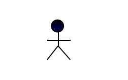 |
· The user interacts with the system. · It must be a noun. · It can be a person, an organization, or an outside system interacting with your application or system. · It must be external objects that produce or consume data. · It must be linked with a use case. |
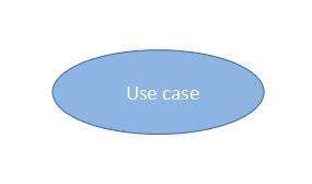 |
Use case · represent the different functions of a system. · Named by a verb or a noun phrase · do not have to be linked with an actor |
 |
Communication link · connects actors with their use case · Actors are connected to use cases by associations |
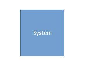 |
Boundary box · Sets a system scope to use cases. · It can be a module for large and complex systems. |
Part 5. Types of Flowcharts
Use case diagrams have different relationship types, which the system analyst defines. Any relationship between the use cases shows the dependency between the use cases. The relationships reduce the effort required to develop a system by reusing an existing use case through the different relationships. There are three main types of relationships, which include extend and generalizations, as described in the diagram below.
| Visual Representation | Use Case Relationship |
|
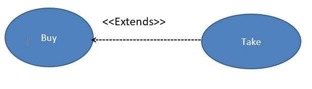
Extends: · Used to specify that one use case (extension) extends the behavior of another use case (base). · This relationship reveals details about the system that are usually hidden in the use case |
|
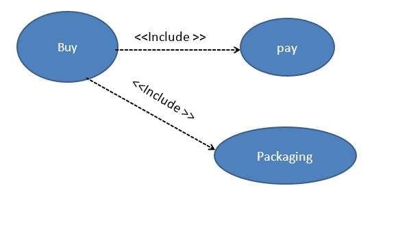
Include: · A relationship in which one use case contains the functionality of another use case. |
|
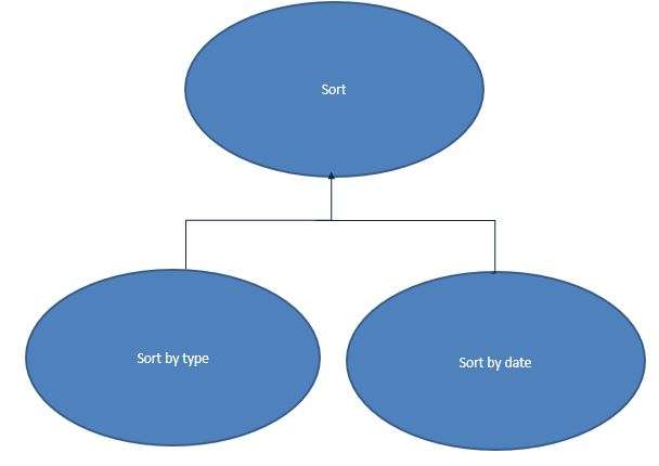
Generalizations: · A relationship in which one model element (child) is based on another model element (parent). · Generalization relations are used in use case diagrams to indicate that the child element accepts all the attributes, operations, and relationships defined in the parent element. |
Part 6. Use Case Diagram Examples
Now to help you further understand what a use case diagram looks like, here are three examples from the templates community of EdrawMax, a free and easy-to-use diagram maker.
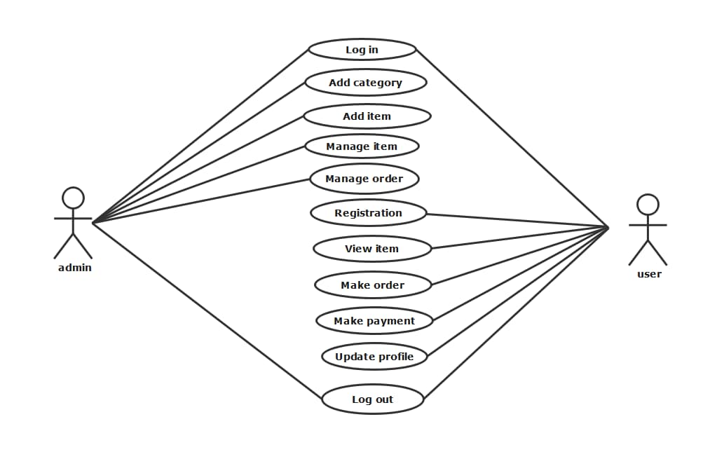
UML Use Case Diagram Online Store
 below.
  below.
 The online organic product shopping system uses a case diagram with two actors, the admin and the user, who interacts with the different use case of the system. The system has eleven use cases where the user logs in, registers for an account, and gets to view items in the online shop. The user can place an order, make payments, update their profile, and then log out. The admin, on the other hand, can also log in, add categories, add the items to the catalog, manage the items and the user's order, and then log out. This use case can be applied in the design and requirement-gathering steps of developing the online store system.
Use Case Diagram for Student Management
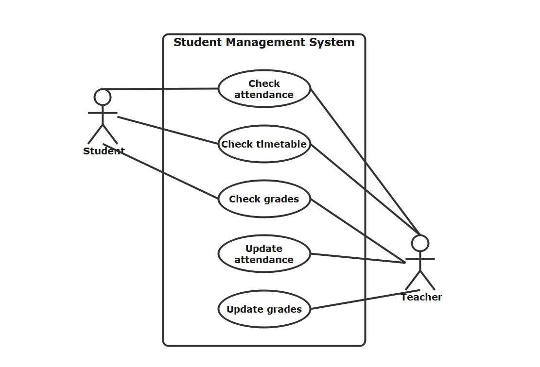
The UML use case diagram represents a student management system with two actors, the student and the teacher. The student can only interact with the system by checking attendance, timetable, and grades. In addition to what the student can do, the teacher can also manipulate the system to update attendance and grades. This use case can be applied while managing, designing, and developing the student management system.
Use Case Diagram For a Website
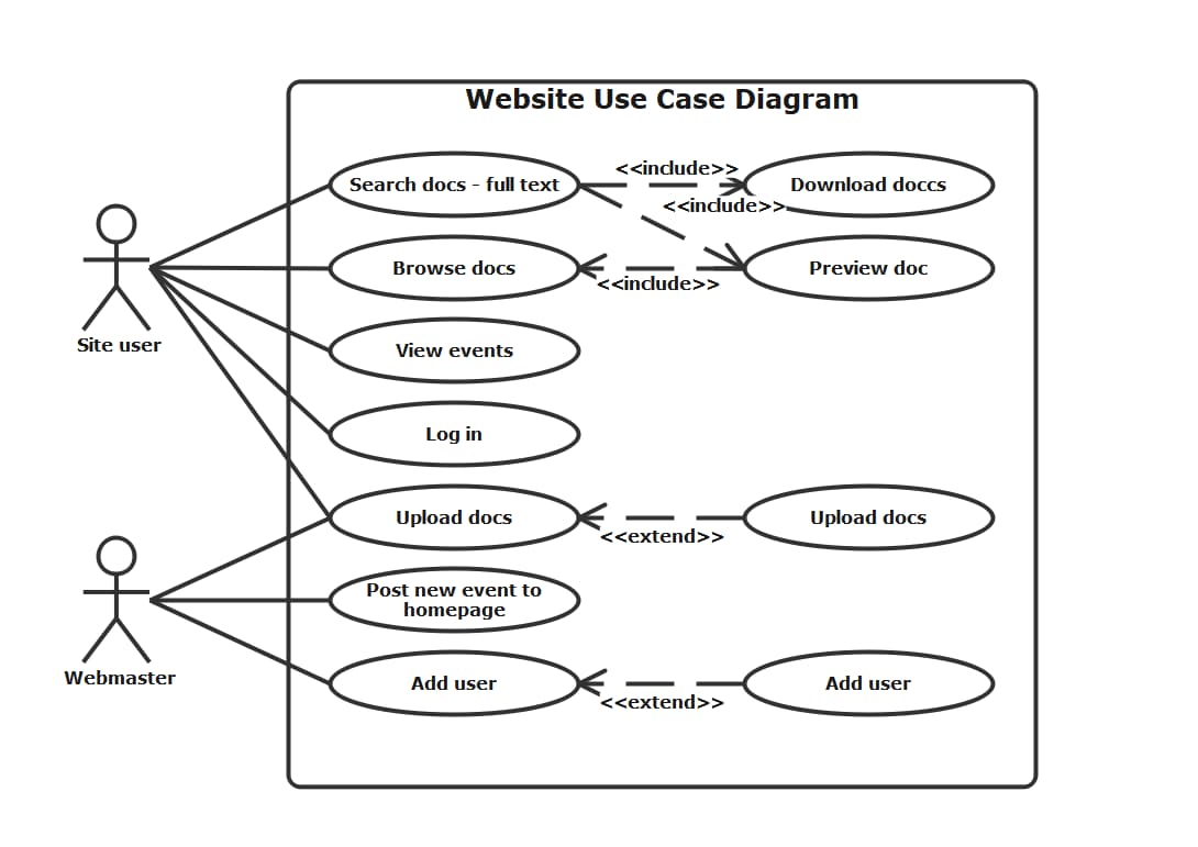
The website use case diagrams clearly outline the actors and functions of the website system. The system has two prevalent actors: the site user with use cases search docs, browse docs, view events, login, upload docs, and the webmaster with use case upload docs, post new event, and adding users. The use case has relationships where search document includes downloading and previewing them. Another relationship is where the add user extends to their company name.
To create an activity diagram, you would need to choose a tool first. If you are looking for a diagram maker that is free and friendly to beginners, try EdrawMax . It has simple and clean user interface similar to MS office and offers over 10,000 free templates of various diagram types for you to get started.
Part 7. How to Make A Use Case Diagram?
Below are some of the steps that you must follow for you to create a use case diagram:
- Identify Actors: first, you must identify all the actors interacting with the system. These must be individuals, other systems, or entities with specific roles.
- Define Use Cases: List the various functions, processes, or actions that the system provides to the actors. These are the use cases, and they represent the system's intended behavior from the user's perspective.
- Establish Relationships: Connect actors to their associated use cases using lines or connectors. These relationships indicate that an actor initiates or participates in specific use cases.
- Include Notations: Use ovals or ellipses to represent use cases and stick figures for actors. Label each with a meaningful name, and use arrows or lines to show the interactions between actors and use cases.
- Add Associations: If certain actors or use cases are closely related, you can add associations to indicate these connections.
- Implement Generalization: For cases where one use case is a more specialized version of another, use generalization to represent inheritance or specialization relationships.
- Include Extending and Including Relationships: When one use case can extend or include another, use dashed arrows to depict these relationships, illustrating optional or extended behaviors.
- Review and Refine: Finally, review and refine the diagram to ensure it accurately represents the system's functionality and interactions.
Part 8. Conclusion
UML use case diagrams are indispensable in system modeling and design. They enhance communication, improve system understanding, and support effective project management. Following this comprehensive guide, you can harness the power of use case diagrams and apply them to various domains, ensuring your projects are well-structured and successful.