


Imagine trying to find a new restaurant without Google Maps—it’d be confusing and time-consuming. That’s exactly what it’s like to navigate a network without a topology diagram. These diagrams act as the blueprint of a network, showing how devices are connected and how data flows between them.
A network topology diagram uses symbols and icons to clearly illustrate the structure of your network and the role of each component. But creating one from scratch can be time-consuming and overwhelming. That’s where EdrawMax comes in. This powerful diagramming tool offers free templates and user-friendly editing features to help you build a professional topology diagram in no time.
Before we explore how to use EdrawMax’s templates, let’s look at a few topology diagram examples to help you get familiar with the different types.
In this article
Free Network Topology Diagram Examples
There are different types of topology diagrams. We will look at examples of each type to help you understand the differences. Since these examples are pre-built templates in EdrawMax, you can use them directly. You can also edit the details to match your requirements.
Example 1: Physical Topology
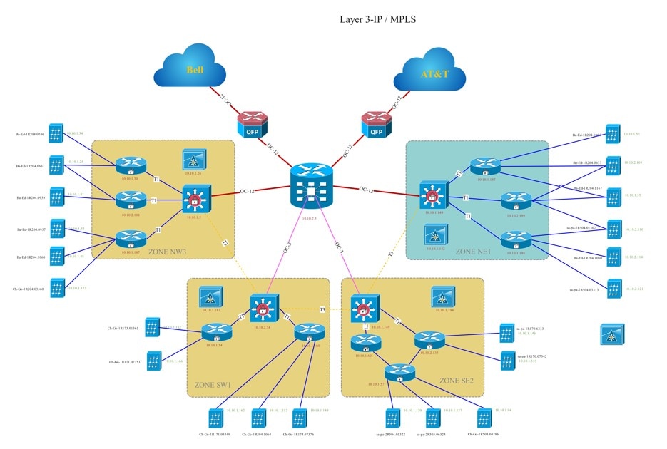
A physical topology diagram shows how the actual hardware in a network is arranged. It highlights the position of each device in a network. This diagram type focuses on the physical aspect of the network, not on how elements communicate. That’s the job of a logical topology diagram. A physical topology simply shows where the devices and wires are in real life.
In this example, you can see how various elements of the network are grouped and placed. The lines and connectors represent the physical links, like cables and wires. This type of diagram is best for networks that are based on different groups and categories.
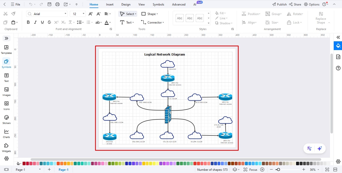
Example 2: Logical Topology
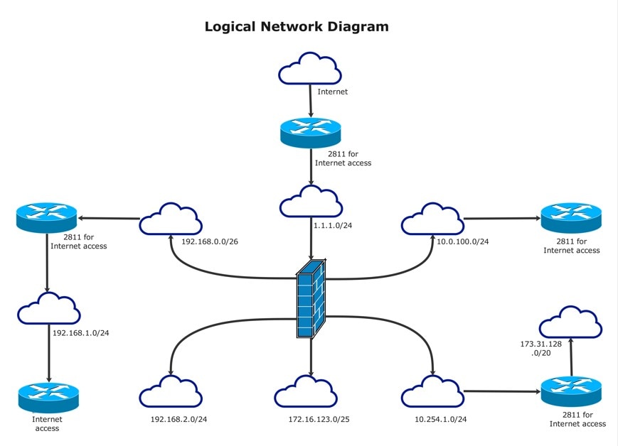
Unlike physical topology, logical topology shows the virtual parts of a network. It shows how devices are connected to each other and the internet. Most of the information represented in these diagrams is not visible or tangible to users. For example, this type of diagram shows how different modules are connected to the internet. It could also depict inter-device communication protocols. Both of these are non-tangible elements of the network.
The example given below highlights the flow of information through modules, devices, and subnets. It features a large central server with five smaller devices placed around it. The arrowheads going around the devices show how information flows from each node to the next. The layout featured in the template is quite basic and generic.
You can use this template to create a logical topology of your own network. You can easily edit the details and modify the positioning of the elements to suit your requirements.
Example 3: Point-to-Point Topology
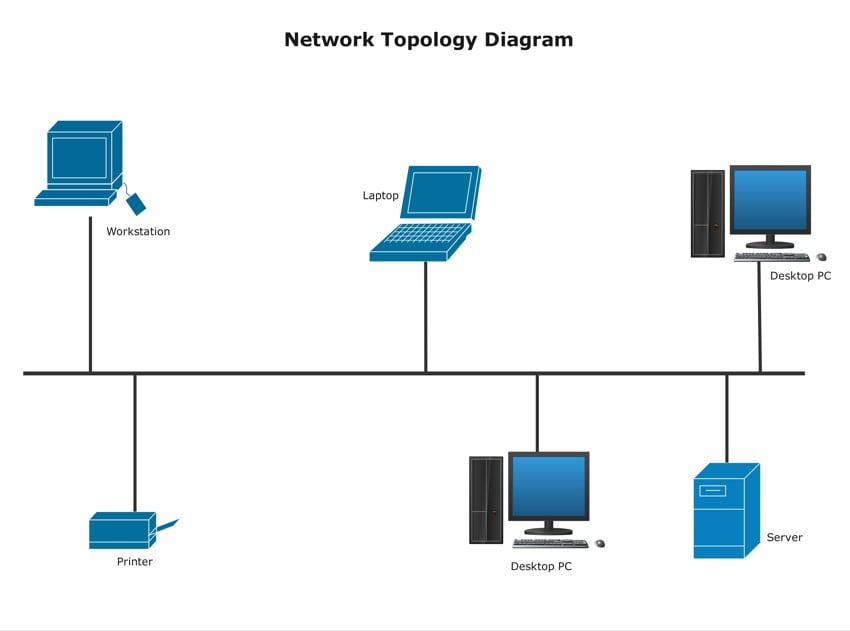
Point-to-point topology is defined as a network in which two modules (devices, routers, servers, etc.) are directly connected through a shared medium. This medium can be a physical wire or a cable, or it can be a wireless connection instead. Point-to-point topologies can consist of just two modules connected with one another. Or they can consist of multiple elements instead.
The following example shows how the different components, i.e., the workstations, laptops, printers, and servers, are all connected to a single shared medium. This medium then connects all of them to form the network.
You can use this template to create topology diagrams for small networks. For example, single offices and a network in a building. The arrangement of the components in this template is simple enough, and you can easily modify it.
Example 4: Star Topology
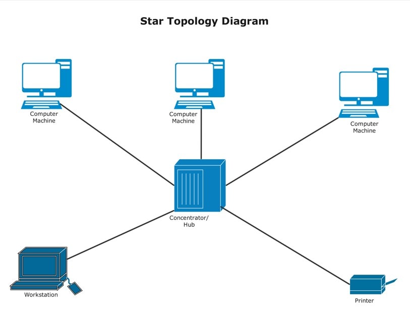
In a star topology, the devices are connected to a central node (which is also known as a 'hub') in a star-like arrangement. The devices and the modules in a star topology can be computers, printers, scanners, workstations, etc.. The central hub can be a server that transmits information between each of the connected components.
Star topologies are one of the simplest and most common network arrangements. They are usually found in offices where users have to communicate with one another through shared devices (printers, etc.).
In the template below, three computers are placed at the top, while a workstation and a printer are placed at the bottom. All these devices are connected to a central hub, labelled 'Concentrator.' You can use this template to show a network layout that consists of multiple nodes and modules connected to a central device.
Example 5: Bus Topology
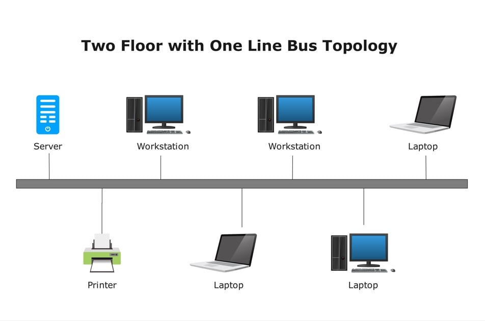
Bus topologies are also known as 'line topologies.' Here, all the elements, like computers, printers, servers, etc., are connected to one main wire or cable. This wire or cable is known as the 'backbone.' In this type of arrangement, the various modules and devices communicate with one another via the backbone. In other words, the information flows from one device to the backbone and then from the backbone to the recipient module.
The following bus topology template shows six different devices. Four of these are computer systems, one is a server, and one is a printer. In this setup, if a computer wants to use the printer or connect to the server, the signal travels through the main line, called the backbone.
The applications of bus topologies are more or less the same as star topologies. For example, both these types of topologies are used when multiple users have to communicate with one another as well as with other shared devices.
Example 6: Mesh Topology
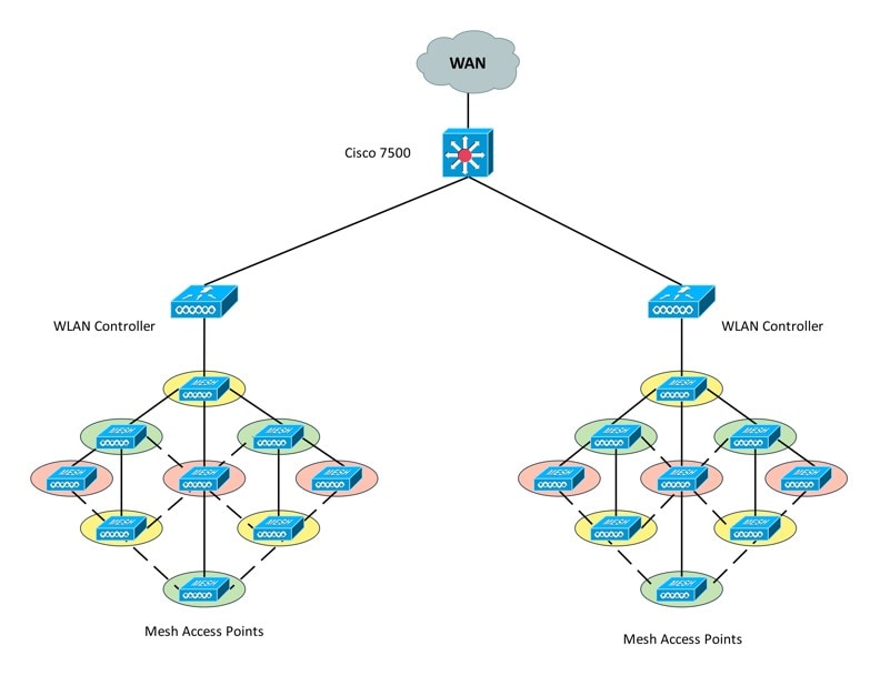
In a mesh topology, all the devices and modules in the network are interconnected. This way, every device can communicate with other devices on the network independently. They don't need any intermediating element (such as a hub or server).
This template shows a mesh topology in two separate but identical sub-networks. Each set of sub-networks is connected to a WLAN controller, which is then connected to a central server. Nowadays, one of the most common applications of mesh topologies is home automation functions. In 'smart' homes, different appliances such as lights, fans, and air conditioners are all interconnected with each other. This is achieved via mesh topologies.
You can use this template to create a layout for devices in an automated home environment.
Example 7: Ring Topology
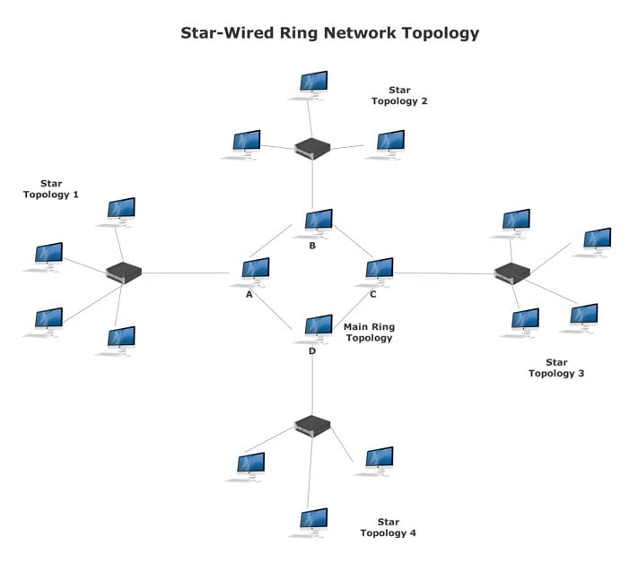
In ring topologies, the devices are arranged in a ring-like, circular shape. Here, each device is connected to two others, i.e., one on its right side and one on its left. So, it's similar to mesh topology in a way. But also different because every device is only connected to two others independently.
In this template, the ring topology is shown right at the center of the diagram. There are four computers arranged in a circular shape. Device B is connected to A and C, whereas A is connected to D and B. This means if device B had to send information to device D, it would have to send it through either A or C. In other words, it is possible for two devices that are not directly connected to share data. But it has to go through the other nodes.
Ring topologies are mostly used in small setups such as homes and offices. In this particular template, you can see that there are multiple star topologies located around the main ring. The ring topology at the center is the central network, whereas the star topologies around it are smaller sub-nets that are connected to it.
Example 8: Tree Topology
A tree topology is an arrangement of multiple star topologies connected through a backbone. So, they are like bus topologies, except for the fact that bus topologies have different devices and modules connected to the backbone, whereas, in a tree topology, whole networks are connected to the backbone.
Tree topologies are usually found in large setups such as multi-floor buildings and offices. You can use tree topology diagrams to show complex networks in an easy-to-understand manner.
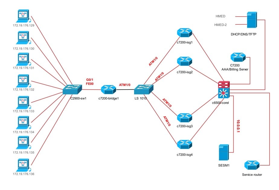
Example 9: Hybrid Topology
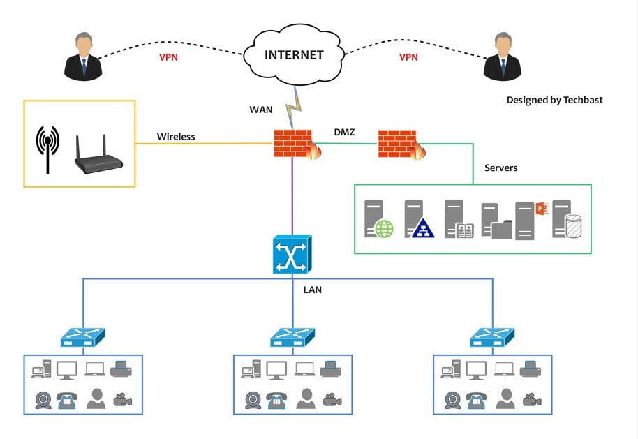
A hybrid topology is a network arrangement that uses two or more types of topologies. In this example template, you can see how the various devices and nodes are connected to one another. On the left side, different computer systems are connected to the C2900-sw1 node in a standard star topology-like arrangement. Whereas the modules in the center of the diagram have a point-to-point arrangement.
How to Use Topology Diagram Templates
EdrawMax is a powerful diagramming tool that’s perfect for creating network topology diagrams. It offers a user-friendly interface with multiple customization options to help you build custom designs. All you need to do is choose a pre-built template that reflects your communication network. Next, you can edit it using symbols and other design features to match your system.
There are two methods of creating a topology diagram using EdrawMax templates. You can either download EdrawMax onto your system or edit the template online. We’ve discussed both options below.
Create the Diagram from Desktop
Step1 Install EdrawMax
Open EdrawMax’s website.Click theDownload button on the top right of the screen.
Follow the required steps to install the software on your desktop.
Step2 Open a Template
Sign up on EdrawMax or use your socials to sign in.
Download any of the above templates and open them in your desktop app.
EdrawMax has a wide template library, so you can search for more options.
Step3 Customise the Topology Diagram
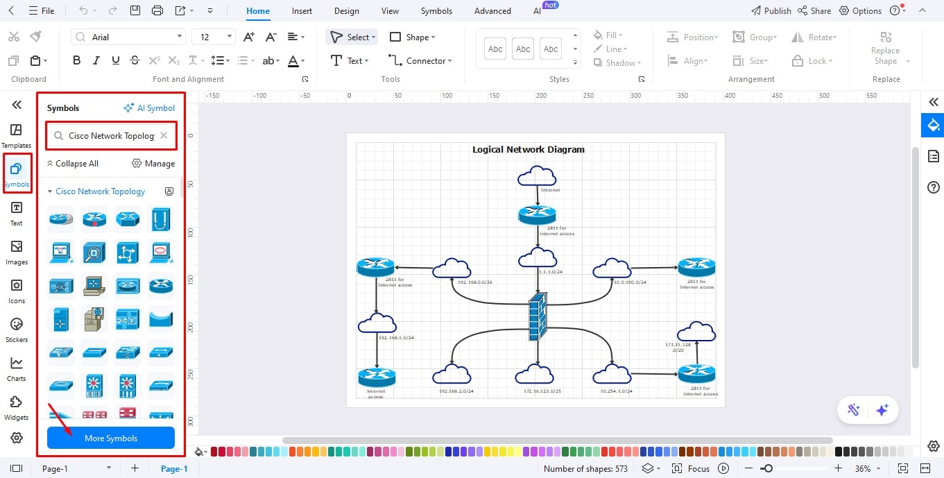
You can edit the diagram and add items like routers, switches, servers, etc., onto your canvas.
For that, navigate to the left editing panel and click Symbols.
Type Cisco Network Topology in the search bar to reveal relevant symbols.
Select the symbols you want and simply drag and drop them on the floor plan diagram.
If you can't find the symbol you need, click More Symbols to access the complete selection of basic drawing shapes, arrows, creative lines, connectors, etc.
You can also change the color and the font style of the template.
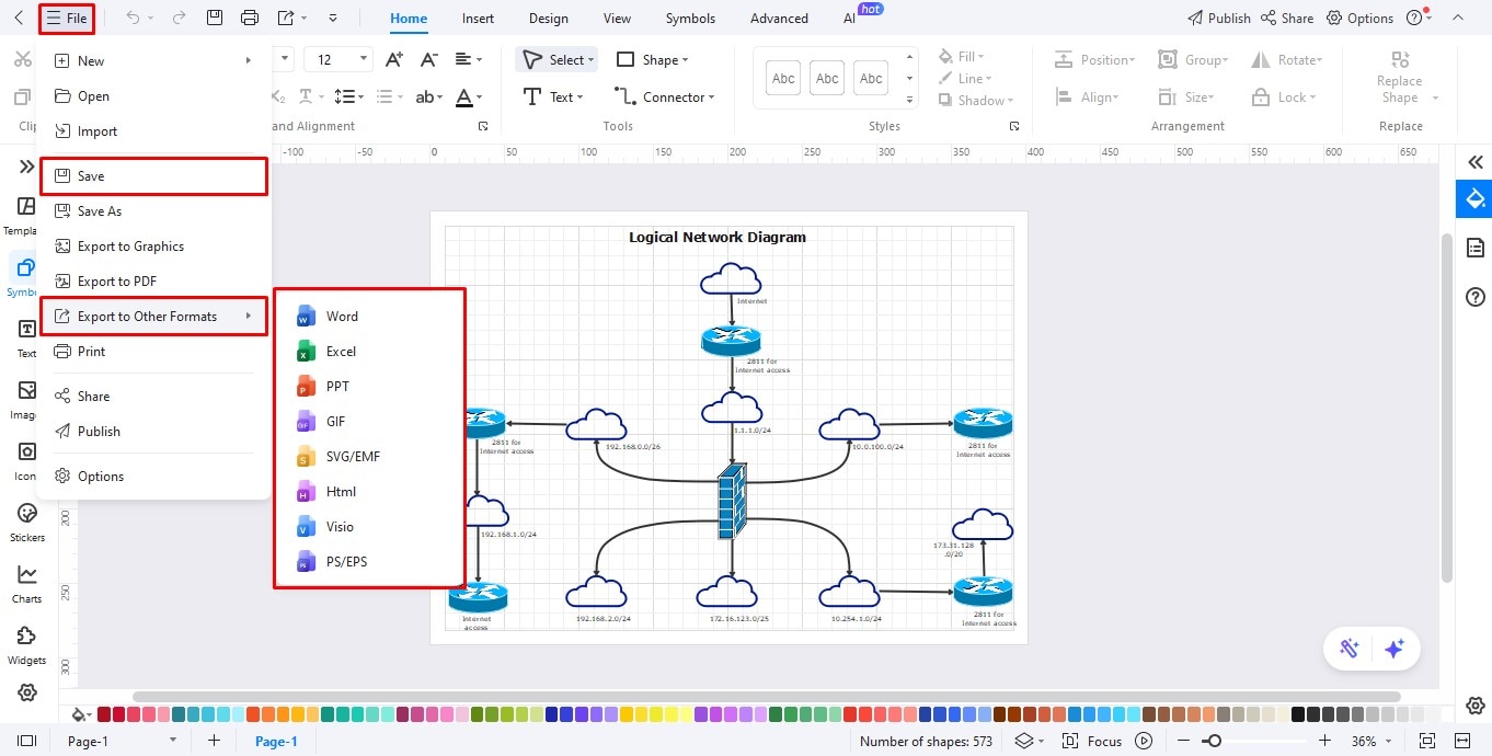
Step4 Save or Export Layout
Once the diagram is finished, you can save or export the file.
EdrawMax supports multiple document formats, including PDF, graphics, and HTML.
To download the drawing, click File from the top menu bar.
Now select your preferred format from the options below.
Create a Topology Diagram Online
Step1
Head to the EdrawMax Online.
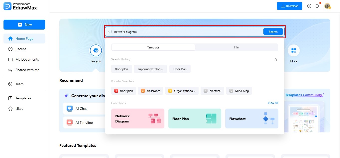
Step2 Search Template
Write Network diagram in the search bar to see community templates.
Browse through the selection until you find a template you like.
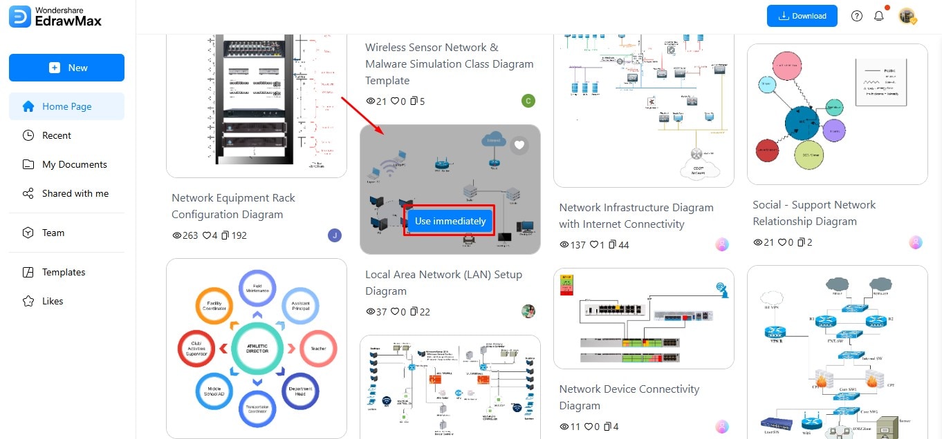
Step3 Select Template
When you find a template, click Use Immediately or double-click on the image to open it in the browser.
You can then customize the drawing using EdrawMax's editing features.
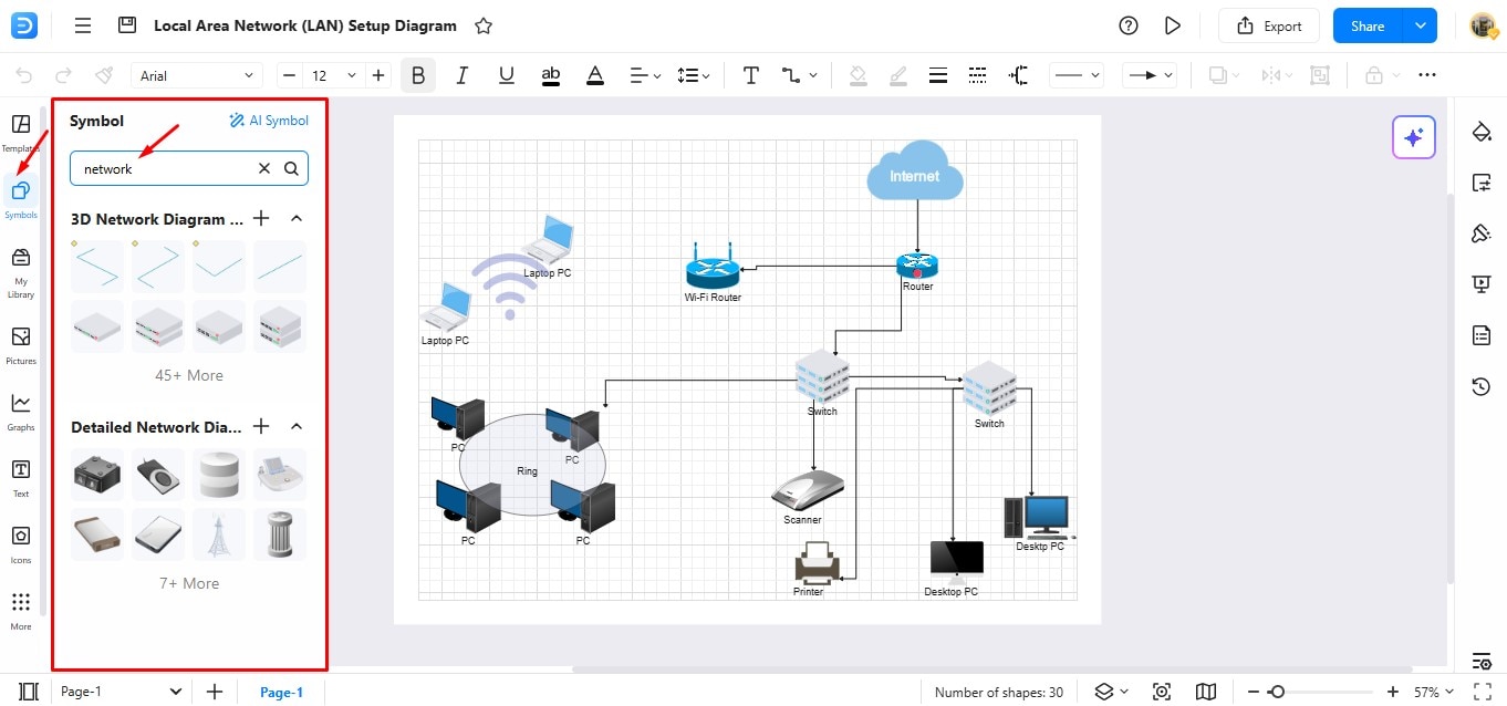
Step4Edit the Template Online
Locate Symbols in the left panel to access the library.
Browse through different categories to find suitable symbols for your topology diagram.
You can also add text, icons, and images to the diagram.
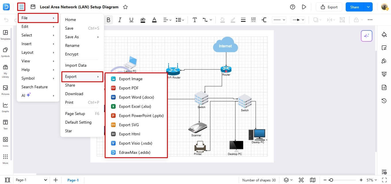
Step5 Export the Template
Once your diagram is complete, you can export it to your system.
Click File on the top menu bar, and choose Export to reveal downloading formats.
Select the format you prefer to download the file.
EdrawMax is a Complete Diagramming Solution
If you want to create topology diagrams for your network, you should try EdrawMax. It is great for beginners and experts. With an easy-to-use interface and extensive customization options, you can create custom designs quickly.
While there is a Pro version available, free users can enjoy a lot of perks even without upgrading. You can use EdrawMax online, and you can download it as well.
Here are some outstanding features of EdrawMax you shouldn’t ignore:
- More than 26,000 icons and symbols in the symbol library
- 25 different color combinations for in-depth customization
- Easy and simple drag-and-drop mechanism
- Multiple exporting options for easy file sharing and sending
- Affordable pricing
Best Design Practices for Topology Diagrams
From a mesh topology to a tree diagram, you need a creative mind to design it. Your general aim when diagramming should be to strike a balance between thoroughness and clarity. Here are a few practical tips you can incorporate for quality diagrams.
Recognize the Industry Norms
A good network diagram is easily understood. So, stick to standard symbols and notations. The more consistent your symbols are, everyone familiar with topology diagrams would be able to interpret them correctly.
Avoid Overcrowding
Try to keep your diagram simple. A lot of information can make it seem confusing and reduce readability. So, choose a clean layout and avoid excessive crossing of lines.
Use the Right Tools
Use a powerful network diagram software to save time and effort. EdrawMax is a great choice as it’s equipped with industry symbols and pre-built templates. Also, remember to update your diagrams regularly to maintain their usefulness.
Label Clearly
Topology diagrams can get confusing, especially when many devices are shown. To keep things clear, label every component and connection properly. Use specific names for devices and lines. Adding notes or annotations can also help explain tricky parts. Avoid being vague. Small details like cable types or encryption levels are often missed, but they matter.
Run a Test on the Diagram
Check your network diagram by reproducing it on a network simulator like GNS3. Then, compare it to the actual setup to see how accurate it is. You can upload virtual computers as network appliances using GNS3 and other tools for research and testing.
Key Takeaways
These examples and tips will help you master network topology diagrams. Whether you’re dealing with network issues or simply ensuring the system’s efficiency, these diagrams will be your go-to tool. The only trick is choosing a diagramming app that lets you create and collaborate on topology diagrams seamlessly.
You need EdrawMax and its powerful visual workplace. So download it today and start exploring its diagramming possibilities.
AI Diagram Generator
Enter your prompt. Upload files if needed. Generate diagrams, charts, or slides instantly.


