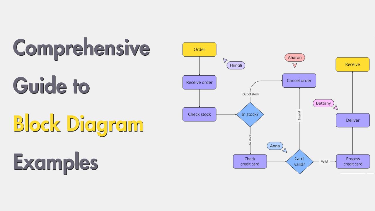
When you’re starting a new system or in the planning phase, you need a block diagram to visually illustrate and explain your idea.
It's a graphical tool used to break down and visualize systems and processes. These diagrams are valuable across various fields, including engineering, software development, and process management. They help professionals design, analyze, and communicate complex systems efficiently.
This guide aims to provide detailed information about block diagrams and their examples across various industries. You will also learn about its benefits and how to create one to help you understand its practical applications.
In this article
What is a Block Diagram
A block diagram is a graphical representation that illustrates a system or process using blocks to represent components and arrows to show relationships and flows. Each block signifies a distinct part of the system, such as a function, process, or hardware component. This type of diagram provides a high-level view, making it easier to understand and communicate complex systems.
Unlike other diagram types, such as flowcharts or circuit diagrams, block diagrams focus on the main components and their interconnections rather than detailed operations or circuitry. This makes block diagram examples particularly useful for system design, analysis, and troubleshooting across various industries.
Examples of Different Types of Block Diagrams
Function Block Diagram (FBD)
The given block diagram example is a Function Block Diagram that illustrates the operational logic of a system. The blocks here represent functions such as sensors, actuators, and control logic, connected by lines to signify the flow of data and signals. This type of diagram is essential for visualizing automation processes in manufacturing and industrial sectors.
One can take help from an online block diagram maker like EdrawMax to describe a concept, process, or system at the beginning of their work. These types of diagrams are helpful in automation and control systems.
Functional Flow Block Diagram (FFBD)
The block diagram example is a Functional Flow Block Diagram that provides a step-by-step representation of a product development process. The blocks include stages such as concept, design, development, and testing, depicting the sequence and interdependencies between these stages.
EdrawMax has templates for creating detailed FFBDs, which are particularly useful in systems engineering and project management.
Software Block Diagram
This block diagram example is a Software Block Diagram that highlights the structural components of an e-commerce platform. The blocks show modules like user authentication, product catalog, shopping cart, and payment processing, illustrating how these interact.
EdrawMax offers customizable templates to help developers visualize and plan software architecture effectively.
Electrical Block Diagram
The given block diagram example is an Electrical Block Diagram depicting a power distribution system. The blocks represent components such as generators, transformers, and distribution lines, showing their interconnections.
The tool in online block diagram maker EdrawMax helps create this type of diagram easily with intuitive drawing tools, making it ideal for designing and troubleshooting electrical systems.
Process Block Diagram
This Process Block Diagram example maps out the sequence of chemical reactions in a chemical plant. The blocks show processes like filtering, distillation, and cooling, highlighting the flow of raw materials to the final product.
Using EdrawMax, process engineers can create PBDs to optimize and streamline manufacturing operations, enhancing efficiency.
UML Block Diagram
The given block diagram example is a UML Block Diagram used in software engineering to depict class hierarchies and object interactions. The blocks illustrate the structure and behavior of systems, making it easier for developers to understand system components.
EdrawMax provides a range of UML templates that can be customized for specific project needs.
PIC (Peripheral Interface Controller) Function Block Diagram
This block diagram example is a PIC Function Block Diagram that shows the functional components of a microcontroller-based system. The blocks detail input/output operations, processing units, and memory.
EdrawMax’s versatile tools enable users to create detailed and accurate PIC function block diagrams, facilitating the development of embedded systems.
The above examples showcase the versatility and utility of block diagrams across various industries. EdrawMax provides a powerful platform for creating, customizing, and optimizing these diagrams. This makes it an important tool for professionals.
Components and Symbols of Block Diagrams
It is essential to understand the components and symbols when working with block diagram examples. Familiarizing yourself with these elements enables you to effectively create and interpret various block diagrams.
These diagrams typically include the following elements:
- Blocks: Represent the different components or functions within the system. Each block is a distinct part, such as a hardware component, a process, or a function.
- Arrows/connectors: Illustrate the relationships and flows between the blocks. They show how different components interact and how data or signals move through the system.
- Labels and text: Provide descriptions and annotations for the blocks and connectors. They add context and clarity, ensuring that the diagram is easy to understand.
- Special symbols: Certain block diagrams use specialized symbols. For instance, electrical block diagrams might include symbols for resistors, capacitors, and other electrical components, while software block diagrams might use icons representing databases, user interfaces, and servers.
How To Make a Block Diagram?
Creating a block diagram is a simple process that can help you visualize complex systems. Here are the general steps to follow, using block diagram examples as a guide:
- Define the purpose and scope: Start by clearly defining what you aim to achieve with the block diagram and the boundaries of the system or process you are illustrating.
- Identify key components and processes: List all the major components, functions, or processes that need to be included in the diagram. This might involve brainstorming sessions or consultations with stakeholders.
- Draw blocks for each component: For each key component or process identified, draw a block. Each block represents a distinct part of the system.
- Connect blocks with arrows to show relationships: Use arrows or connectors to link the blocks, illustrating how they interact and how data or signals flow between them.
- Add labels and descriptions: AInclude labels and brief descriptions for each block and arrow, providing context and making the diagram easier to understand.
- Review and refine: Finally, review the diagram to ensure accuracy and clarity. Make any necessary adjustments to improve readability and comprehensiveness.
Benefits of Block Diagrams
Using block diagram examples offers numerous advantages across various fields. Here are some key benefits:
- Simplifies complex systems and processes: Block diagrams break down intricate systems into understandable components. This simplification makes it easier to grasp the overall structure and operation.
- Enhances understanding and communication: These diagrams provide a clear visual representation that enhances comprehension. They help convey complex ideas between team members, stakeholders, and clients without technical jargon.
- Facilitates troubleshooting and problem-solving: By visually outlining the system, block diagrams aid in identifying and isolating issues. This facilitates quicker troubleshooting and effective problem-solving by pinpointing problem areas.
- Provides a clear visual representation: Block diagrams offer an organized way to present data flows, processes, and system architecture. This clarity ensures that everyone involved has a consistent and accurate understanding of the system.
Integrating block diagram examples in your workflow can significantly enhance the design and analysis of complex systems, which ultimately improve project outcomes.
Conclusion
Block diagrams are very important for simplifying and visualizing complex systems across various industries. In this guide, we explored various block diagram examples, including their types, components, and symbols. We also discussed the steps to create block diagrams and highlighted their numerous benefits, such as simplifying complex systems and enhancing communication.
Making a block diagram no doubt requires brainstorming, expertise in graphics designing, and compatible software. Speaking of all of these requirements, EdrawMax proves to be useful in brainstorming, easy designing and compatibility. All you need is picking a template or start from scratch. EdrawMax will help you along the way to make an effective block diagram and more importantly, allow you to present it in a snap! Give it a try, it is totally free for all.


