


Struggling to explain system flows? PlantUML helps you draw sequence diagrams fast. Simply type in text, no design skills required.
Learn key patterns for APIs, microservices, and error handling. See real examples you can use right away. Try it now and create your first diagram in minutes!
In this article
- What is a Sequence Diagram?
- What is PlantUML
- How to Make a Sequence Diagram in PlantUML
- Understanding Sequence Diagram Components
- Advanced Sequence Diagram Features
- Styling and Layout in Sequence Diagrams
- Free Sequence Diagram Examples using PlantUML
- Common Mistakes and How to Fix Them
- Limits to Consider when Using PlantUML
- More Methods to Make a Sequence Diagram
- GUI Tool Options
- Summary
What is a Sequence Diagram?
To engineer software, it is all about clear communication, particularly in comprehending the behaviors of the systems in question. Sequence diagrams are one of the most effective methods for recording a system's behavior; they represent the interaction among objects, systems, or users chronologically.
Sequence diagrams are a subset of UML (Unified Modeling Language) diagrams that are most successful at representing time-ordered flows of messages. In contrast to static diagrams, such as the diagram of the classes or the component diagrams, the sequence diagram helps to highlight the dynamic flow one experiences, i.e., the real communications (exchanges of components) during a transaction or work.
Such diagrams can assist with the following questions:
- What are the services in this operation?
- How do calls occur?
- How will the response be expected at every step?
- Where would breakdowns or delays set in?
Sequence diagrams are commonly used in mapping interactions, and they are quite easy to interpret and explain. This makes them important to use in complex architecture, systems, and API designs. They are especially useful when you are defining or considering interaction in microservices, noting how legacy processes are done now, or how a system would behave in various circumstances.
When they work with sequence diagrams early during the design process, teams avoid miscommunication problems, minimize integration problems, and bring everyone, including backend engineers and product managers, to align on the system's behavior.
What is PlantUML
Diagrams are a visual aid to software engineering languages. From class structure design through workflow mapping and API documentation, effective visual communication saves time and minimizes confusion. Of the numerous available tools, none is more developer-centric or beautifully integrated with contemporary software practice than PlantUML, a text-based diagramming language.
PlantUML is not only a UML tool; it is also a powerful, general-purpose diagramming engine; you can use it to create sequence diagrams, class diagrams, activity flows, use case diagrams, ER diagrams, wire frames, and more. All from plain text.
No matter if you're an architect, developer, business analyst, or product owner, it helps to boil down and clarify the abstract logic of your interpretation into visualizations to improve your understanding and the collaboration around it.
Unfortunately, traditional tools like Visio or Lucidchart don't always make this easy, and are clunky, slow, or just not suitable for the pace and flow of DevOps. PlantUML allows easy integration into your development lifecycle.
This handbook is your full-spectrum guide to PlantUML expertise, with coverage of syntax, advanced styling, automation, and real-life scenarios. It's targeted to engineers, analysts, architects, and technical writers who are looking to clean up their documentation under version control, and with the ability to be automated.
Why Use PlantUML?
- Text-based: Simpler version control and simpler to review in diffs with a straightforward to learn syntax.
- Tool-friendly: Supports Markdown, HTML, Doxygen, Confluence, GitHub, and CI tooling. Simple integration with IDEs, CI/CD pipelines.
- Automation-ready: Conveniently rendered through the command line or Docker.
- Extensible: Macros, includes, and skins support complex modular configurations.
- Low footprint: Light and open-source. Supports Mermaid, Markdown renderers, and more.
How to Make a Sequence Diagram in PlantUML
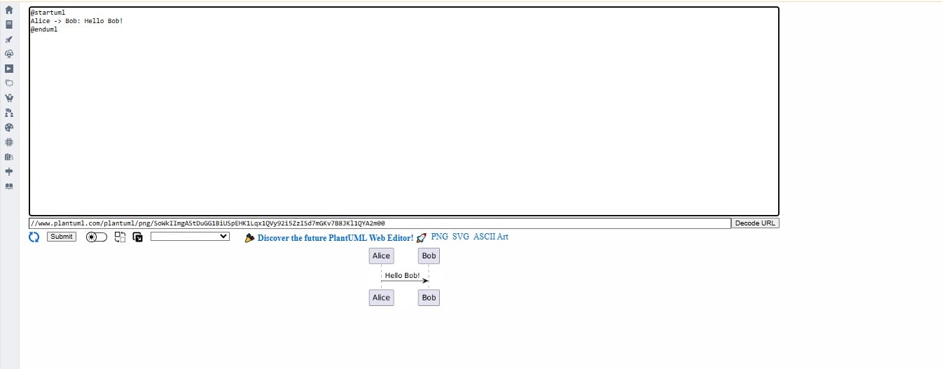
To dive deep into the understanding of how to make sequence diagrams via PlantUML, here's a basic form of it.
@startuml
Alice -> Bob: Hello Bob!
@enduml
Breakdown
@startumland@endumldefine the start and end of the diagram.Alice -> Bobrepresents a message being sent from Alice to Bob.- The colon: it represents or adds up a label indicating any message, like in this case, it's "Hello Bob!"
- Result: A visual diagram with a timeline and two participants showing a one-way communication.
Understanding Sequence Diagram Components
PlantUML provides rich syntax to express a wide range of real-world interactions.
Participants
Participants are entities in the diagram—users, services, or components.
@startuml
participant "Web Client" as WC
participant "Auth API" as AA
@enduml
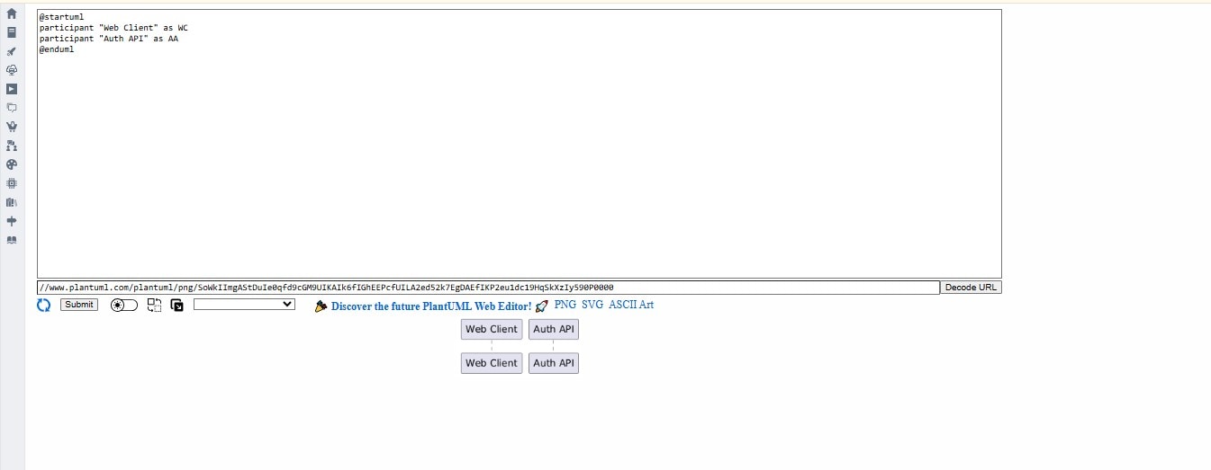
Use the participant keyword to name them. Aliases (as WC) make labels shorter.
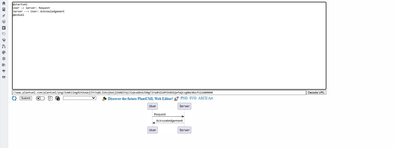
Messages
- Synchronous: solid arrow
-> - Asynchronous: dashed arrow
--> - Return: reversed arrow
<--or<-
User -> Server: Request
Server --> User: Acknowledgement
Activation Boxes
Activation bars show when a participant is actively doing something.
@startuml
Alice -> Bob: Start Process
activate Bob
Bob --> Alice: Done
deactivate Bob
@enduml
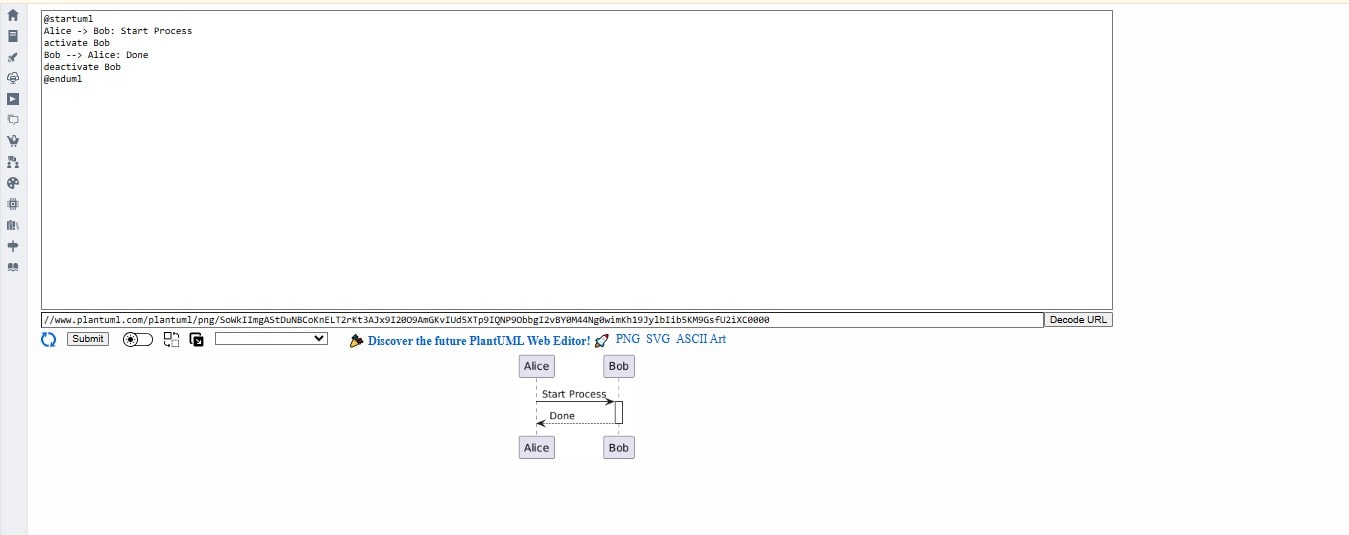
This makes timelines more precise and indicates processing time.
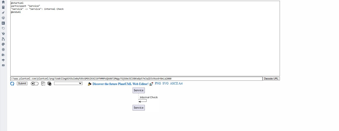
Self-Calls
An object can call itself—useful for internal processing or recursion.
@startuml
participant "Service"
"Service" -> "Service": Internal Check
@enduml
Full Example: User Login Flow
@startuml
actor User
participant "Frontend" as FE
participant "Auth Service" as AS
participant "Database" as DB

User -> FE: Enters credentials
FE -> AS: Authenticate()
AS -> DB: Validate credentials
DB --> AS: Valid
AS --> FE: Auth token
FE --> User: Welcome Page
@enduml
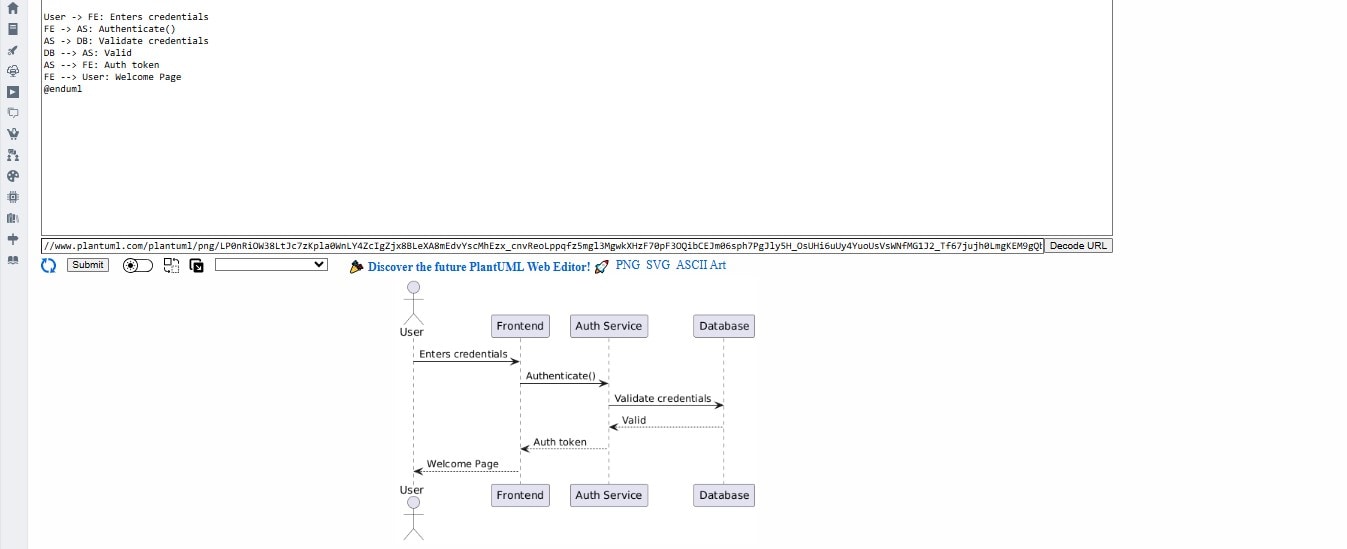
What This Shows:
- The flow of a login interaction from the UI to the backend
- Internal validation via a database
- Return of a session token and response to the user
- This is a common pattern in web apps and microservices.
Advanced Sequence Diagram Features
Once you're comfortable with the basics, here are more advanced tools PlantUML offers.
Loops and Conditions
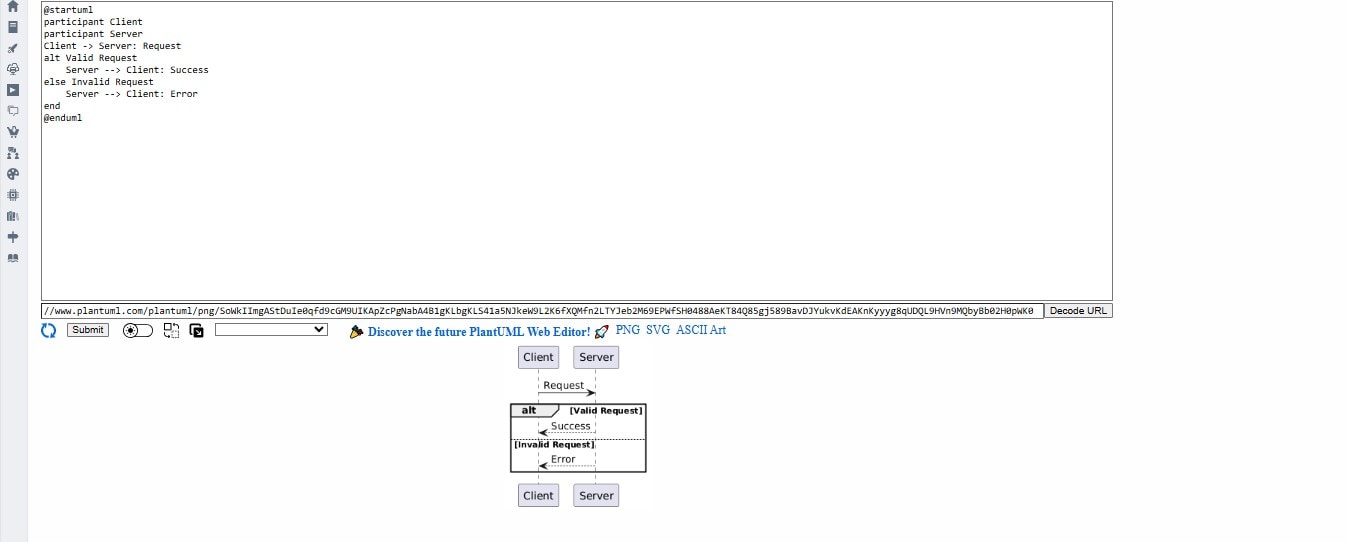
Conditional Flow:
@startuml
participant Client
participant Server
Client -> Server: Request
alt Valid Request
    Server --> Client: Success
else Invalid Request
    Server --> Client: Error
end
@enduml
Loops:
@startuml
participant Worker
loop Every 5 seconds
    Worker -> Worker: Poll Queue
end
@enduml
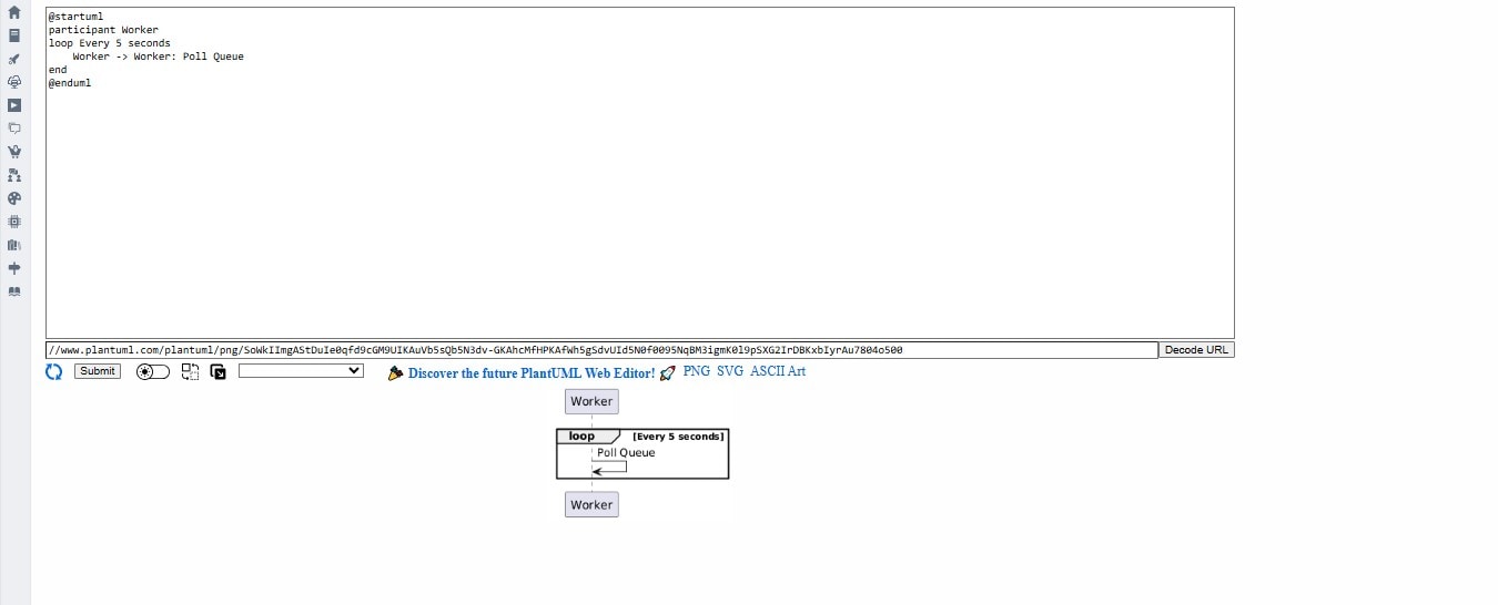
These help model real systems with retries, conditions, and branching behavior.
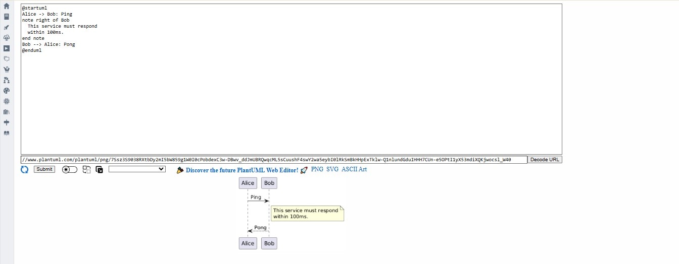
Notes and Annotations
Notes add clarity for documentation or presentation purposes.
@startuml
Alice -> Bob: Ping
note right of Bob
  This service must respond
  within 100ms.
end note
Bob --> Alice: Pong
@enduml
Grouping and Fragments
@startuml
group Login Flow
  User -> AuthService: Submit Credentials
  AuthService --> User: Token
end
@enduml
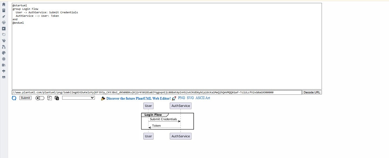
Group blocks help logically separate interactions (e.g., signup, payment, etc.).
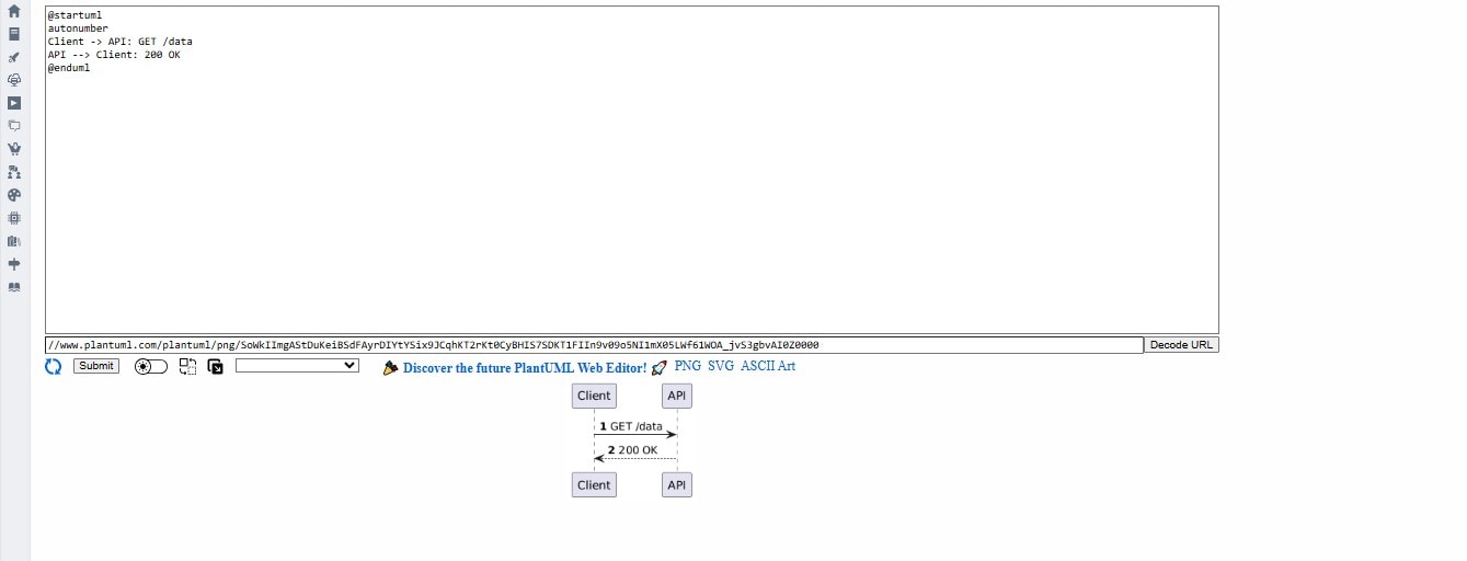
Auto-Numbering
You can add sequence numbers to each interaction:
@startuml
autonumber
Client -> API: GET /data
API --> Client: 200 OK
@enduml
Styling and Layout in Sequence Diagrams
While the default output of PlantUML is readable, applying consistent styling and layout improvements makes your diagrams easier to understand, especially as complexity grows. PlantUML provides several customization options that control the visual appearance of sequence diagrams without altering their logical flow.
Skin Parameters
Use skinparam to globally style your diagrams. You can control arrow colors, fonts, background colors, spacing, and more.
@startuml
skinparam backgroundColor #F5F5F5
skinparam sequenceArrowColor DarkBlue
skinparam sequenceParticipantUnderline false
skinparam participantPadding 20
@enduml
These parameters make your diagram easier on the eyes and better aligned with your organization's branding or documentation style.
Themes
PlantUML also includes built-in themes. These affect fonts, colors, and participant shapes. To apply a theme:
@startuml
!theme sketchy-outline
participant User
participant Service
User -> Service: Send Request
@enduml
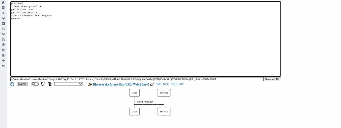
Popular themes include:
- sketchy-outline: Hand-drawn style for informal diagrams
- mars: Dark, minimal look
- cerulean: Bootstrap-like UI feel
You can explore available themes on plantuml.com/theme.
Layout Control
PlantUML allows subtle layout adjustments to improve clarity:
Control Message Order:
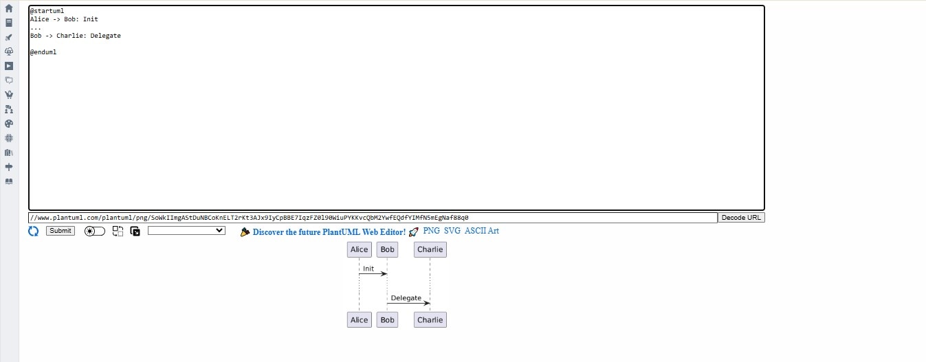
You can control vertical spacing by inserting ... between messages:
Alice -> Bob: Init
...
Bob -> Charlie: Delegate
Control Direction and Spacing:
While sequence diagrams naturally flow top-down, you can manually adjust participant positions with order:
participant A order 10
participant B order 20
participant C order 30
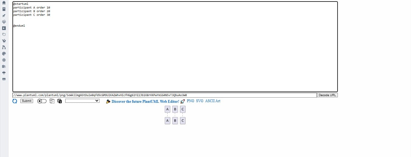
This helps when you want to reorder lifelines without changing the code order.
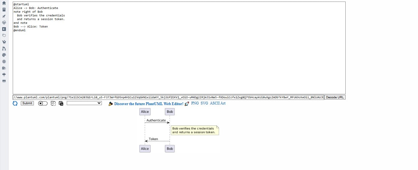
Using Notes for Clarity
Use notes liberally to explain what's happening between steps, especially if the audience is less technical.
@startuml
Alice -> Bob: Authenticate
note right of Bob
  Bob verifies the credentials
  and returns a session token.
end note
Bob --> Alice: Token
@enduml
Hiding Unused Lifelines
If you want to keep your diagram focused, you can declare a participant but avoid rendering its lifeline:
hide lifeline
participant "Cache Service" as Cache
Best Practices:
- Stick to 4–6 participants per diagram for readability.
- Align related messages vertically.
- Use consistent colors for types of participants (e.g., users = gray, services = blue, databases = green).
- Always include arrows and response lines to avoid ambiguity.
- Group related actions using group, alt, or loop blocks for logical organization.
Having a wiser use of the styling and layout features, your diagrams will not only work but will convey an improved and more professional way of communication. Clean looking visuals will also make your documentation easier to keep up with and grow with when working between different teams or stakeholders.
Free Sequence Diagram Examples using PlantUML
The sequence diagrams are not only a theoretical thing but are needed in real-world systems, particularly in distributed and event-driven systems. Three realistic examples have been provided below on how one can use sequence diagrams to model the interaction of various software systems.
Order Processing in E-Commerce
This models how an online store processes an order after the user checks out.
@startuml
actor Customer
participant "Web Store" as UI
participant "Order Service" as Order
participant "Inventory System" as Stock
participant "Payment Gateway" as Payment

Customer -> UI: Place Order
UI -> Order: Create Order
Order -> Stock: Reserve items
Stock --> Order: Confirm availability
Order -> Payment: Process payment
Payment --> Order: Payment Success
Order --> UI: Order Confirmed
@enduml
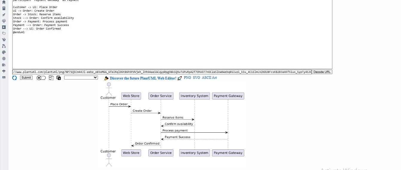
What it shows:
- Component orchestration across systems
- Synchronous and asynchronous flows
- Dependency between stock validation and payment
Microservice API Request with Retry Logic
This models a backend API requesting an external third-party API with retry logic in case of failure.
@startuml
participant "App Backend" as App
participant "External API" as API

App -> API: Request Data
alt API Fails
    API --> App: Error 500
    App -> API: Retry Request
    API --> App: Success
else API Success
    API --> App: Success
end
@enduml
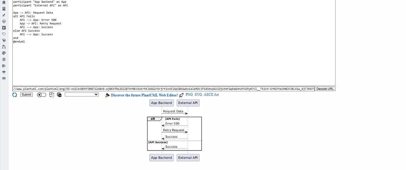
What it shows:
- Use of alt blocks for conditional responses
- Retry logic visualized clearly
- External dependency handling
Event-Driven Notification System
This models how a system sends notifications using a message queue after a user triggers an action (like completing a purchase).
@startuml
actor User
participant "E-Commerce App" as App
participant "Message Queue" as MQ
participant "Notification Service" as Notify
participant "Email Server" as Email

User -> App: Complete Purchase
App -> MQ: Publish event (OrderPlaced)
MQ -> Notify: Consume event
Notify -> Email: Send confirmation email
@enduml
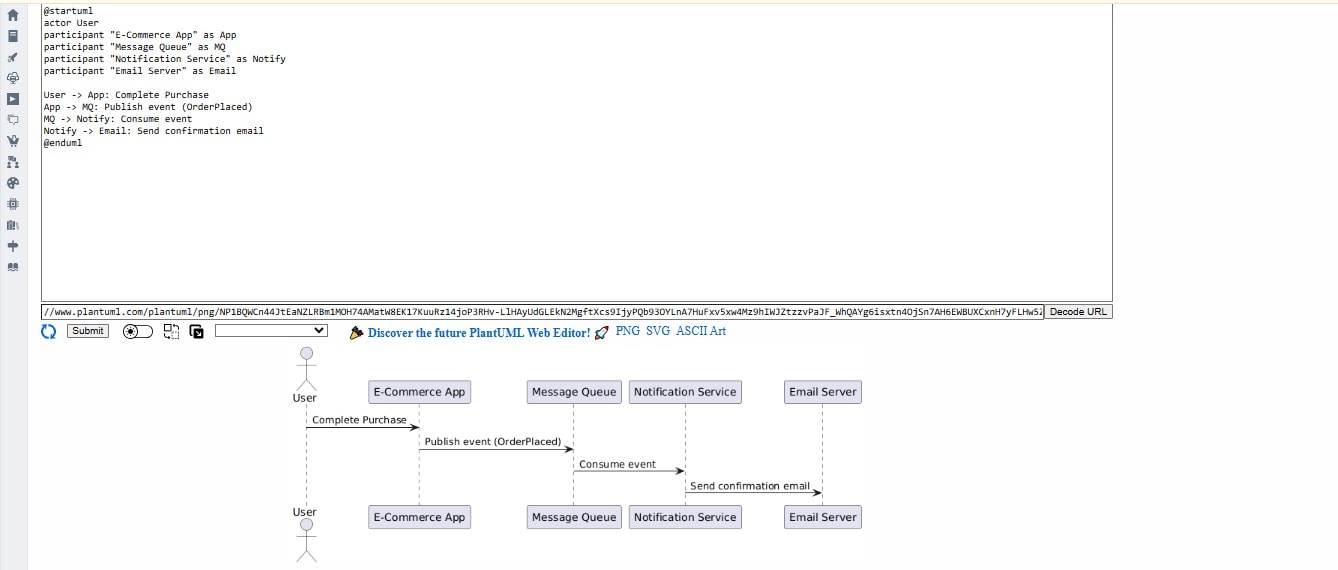
What it shows:
- Decoupling between services using a message queue
- Asynchronous event consumption
- From one end to the other, with user action and system notification
This is typical of microservices and serverless systems, in that services raise and respond to events, as opposed to communications between services. These are just a few of the examples of real development contexts in which sequence diagrams can be very useful, be it developing a system, writing an API specification, introducing a new user, or diagnosing a disaster.
Mistakes When Making a Sequence Diagram with PlantUML
| Issue | Fix |
| The diagram doesn't render | Check @startuml / @enduml placement |
| Arrow direction wrong | Use -> for outgoing, <- for incoming |
| Too cluttered | Break into sub-diagrams or group steps |
| Actors undefined | Always define participant, actor, or entity |
| Missing lifeline activation | Use activate/deactivate for clarity |
Limits to Consider when Using PlantUML for Sequence Diagrams
PlantUML is a powerful and very flexible tool, especially for developers, but it does have the following limitations to keep in mind:
- Style limitations: Customization is quite limited in comparison to GUI tools. You won't be able to manipulate the text placement or spacing, or the curves in lines, very much apart from the most basic skin parameters.
- Difficult learning curve for complex logic: While the basic syntax is quite simple, keeping the plain text logic reasonably simple can be very hard because the flow of complex logic, which includes things like loops, conditions, and notes.
- No real-time collaboration: While applications, for example, Miro or Lucidchart have painless real-time co-editing and built-in commenting, PlantUML completely lacks anything like this.
- Very limited visual previews: If PlantUML is not already tied into your IDE or CI pipeline, rendering and previewing diagrams typically requires you to resort to separate tools as part of your workflow.
- Not user-friendly for visual-first stakeholders: Business users will find text-based diagrams the least user-friendly approach, especially when going to a client.
It is fair to say PlantUML works very well for development teams who value controls around automation, version control, and markdown features. However, if you are after a high-polished visual or real-time diagramming experience, GUI alternatives may be more suited for you.
More Methods to Make a Sequence Diagram
Although PlantUML is a very powerful and convenient tool that supports version control and text-based diagrams, it is not always the correct choice for teams and use cases. Here are some situations to think about alternatives:
Think about alternatives at:
- You require advanced visual design: PlantUML allows for limited styling or design as it cannot compete with drag-and-drop tools like Lucidchart, Visio, or Draw.io, which have pixel and custom visual control capabilities. You also want to embed visualization and images in your documentation.
- Your audience is non-technical: When stakeholders remember that they prefer visual-first tools in real-time editing fashion, node structures might not be the best for usability or accessibility.
- You need collaboration in real time: While PlantUML works great in the gentle nudging and shoving git workflows. It does not allow for effective collaboration with live co-editing or in real-time commenting like Miro or FigJam.
- You are collaborating on historic or complex diagrams: While tools like Structurizr and Archimate can support your standard visual ways for collaborating on huge systems or overviews with diagram tools. While tools like Diagrams.net can layer copying, huge diagrams can equally cause people to miss contextual information or lack performance.
PlantUML Alternatives to Make a Sequence Diagrams
Mermaid:
(Syntax, Support) Easier syntax for collaborating and living documentation. Great for markdown-heavy workflows and comparatively quick diagrams from diagramming repositories in GitHub or Obsidian.
Draw.io / Diagrams.net:
Complete free GUI tool with smooth Google Drive or Confluence integration.
Visio: A familiar, enterprise-friendly diagram tool for those in the workplace who would appreciate solid formatting and smart integrations.
A Desktop alternative to Visio with rich template support.
Use the right tool for your context–PlantUML is great for documentation-as-code workflows, but there are better tools with more UX or visual polish for work delivered to clients.
GUI Tool Options (Neutral Reference)
If you have a team that prefers WYSIWYG editing to code Diagrams, GUI (graphical user interface) tools such as EdrawMax, Lucidchart, or Draw.io have the following advantages:
- Templates and ready-made stencils
- Very easy drag-and-drop interface
- Real-time collaboration features
- Export to PDF, PNG, or SVG
These tools are well-suited to non-developer users, quick mock-ups, and client-facing documentation that requires polish visually without needing to work in a text format.
Summary
Sequence diagrams are valuable for visualizing how systems behave rather than just what they are. Creating sequence diagrams with PlantUML adds speed, clarity, and version control to your documentation.
Being plain text means PlantUML can fit cleanly into CI pipelines, Git repositories, and team documentation tools. It provides developers and architects with a clearer way to work together, while at the same time enabling them to keep diagrams close to the code they are documenting.
Whether you are documenting a single API call or an entire distributed system, PlantUML allows you to turn thoughts into diagrams that you can rely on and maintain, without ever launching a drag-and-drop UI.