


An Insulated Gate Bipolar Transistor (IGBT) is a semiconductor device commonly used in high-voltage applications. Combining the fast switching capability of a MOSFET with the high current-handling capacity of a BJT, it serves as an efficient and reliable component in modern power electronics.
In this guide, we are going to explore:
- What is an IGBT
- Block diagram of IGBT
- Construction and Working Principle of IGBT
- Applications of IGBT
In the end, you will be able to know how to create a block diagram and what benefits you can gain from such diagrams. You will also learn how these devices are benefiting our latest devices.
In this article
IGBT Block Diagram and Its Working Principle
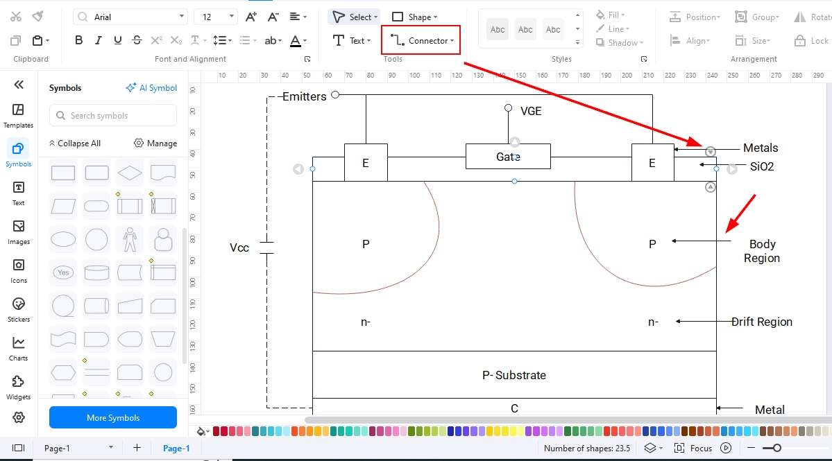
An IGBT block diagram is helpful while learning its complex circuitry and working principle. Here is the complete block diagram for the IGBT.
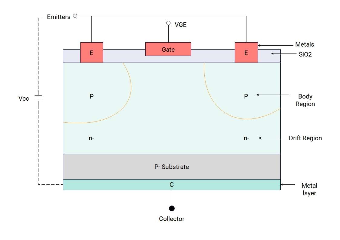
IGBT incorporates the PN junction, which is suitable for high voltage circuits and steady current flows. The main trigger points in the IGBT are the emitter, gate, and collector.
The Collector-Emitter and Junctions
The collector-emitter is connected to a voltage battery, where the collector is attached to the positive terminal and the emitter is connected to the negative terminal. There are two junctions in the System, known as J1 and J2. J1 Junction becomes forward biased and J2 becomes reverse biased, helping the electrons to flow from one region to the other.
Applied Gate Voltage
Once the gate voltage is applied, the electrons start to move towards the p-channel right underneath the SiO2 layer. When this applied gate voltage increases, electrons move rapidly and reach the upper p-region.
Movement of Electrons and Holes
The electrons and holes play a role in the Working of the IGBT. The electrons from the emitter start to move from the emitter to the N+ region, and the holes from the collector begin to move into the N-drift region. The excess of electrons and holes in the N region causes the current flow.
Cut-off Region
When the voltage applied to the System is zero, you have a nonconductive condition at that point, and no charge flow happens. This State is known as an offset State, and the current through the circuit remains zero.
Active Region
When the threshold voltage is breached by the voltage applied, the current starts to flow towards the gate, and negative charges start to flow towards the p region. The current flows from the collector to the emitter in this region. This State is known as an active State.
Conduction
A small voltage applied to the active region is amplified by the circuit, giving enough current to the circuit to run powerfully. The SiO2 layer is there to isolate the metal layer from the gate. This layer prevents the circuit from leaking current and acts as a bridge, making the device more reliable and efficient.
The saturated State
The gate's role is vital to prevent any leakage and to control the current to a constant value. Even if the voltage applied increases to a steady level, the current flow value remains the same. This State is known as the saturated State for which IGBTs are programmed.
IGBTs come in handy when voltage fluctuates and are valuable at high voltages and power. In contrast, MOSFET is suitable for applications where low to medium voltage is applied.
Applications of IGBT
IGBT has numerous applications and is used for both AC and DC circuits to control the current flow and circuit power. Here are a few of the applications of IGBT.
AC/DC motors
Constant current helps AC and DC motors control their speed. IGBT prevents over-speeding and makes motors work at a steady speed, avoiding any damage to the running motors.
UPS (Uninterrupted Power Supply)
IGBTs are very important in UPS devices as there is a need for continuous current flow at a certain voltage. They provide smoother current flow and restrict any damage to the appliances working under the UPS.
Solar Invertors
IGBT chips are used in solar inverters to maintain the current flow. Solar panels are used to generate DC, and most of the home appliances work at AC. The IGBTs are vital to make this conversion from DC to AC currents.
Appliances that Generate Heat
Most home appliances, including the electric cooker, oven, iron, and furnace, are used to create heat. Under a certain voltage, these devices might heat up and explode. The IGBT controls the current value at certain levels for user safety.
Lighting Systems
The IGBTs are used in the lighting systems. They help provide the maximum voltage pulses to the System to maintain the maximum light. Most of the lights use these devices to avoid overheating, as they provide fast switching and control the amount of current. That is why they are the best fits for the street lights, stadium lights, and industrial lights.
How to Create an IGBT Block Diagram
EdrawMax, being one of the top diagramming tools, is helpful in creating comprehensive block diagrams. Let's check out a few of the features of EdrawMax.
- User-Friendly Interface: EdrawMax comes with a user-friendly interface that makes it helpful even for newcomers. It provides a clean interface, drag and drop functionality, image addition, text formats, and much more.
- Vast Library of Symbols: EdrawMax's library of symbols is vast, providing all the symbols, elements, and text formats you need to complete your block diagram.
- Customization Tools: EdrawMax is full of tools offering different color schemes you need for your blocks, text formats, and themes. It provides connector tools to add relationships among the blocks.
- Templates Library: EdrawMax offers templates for each category, helping you complete your own design through these templates. You can use a template as it is if it fulfils your demands.
- Multiple Export Options: EdrawMax is helpful for a wide audience, enabling them to import and export their block diagrams in different formats. You can import Visio files and directly edit them.
Now, let's check out how to create an APU Block diagram with the help of EdrawMax using different methods.
Method 1: Make an IGBT block diagram from Scratch
EdrawMax, as a specialized diagramming tool, provides all the customization tools to start with. Here is a step-by-step guide for you to follow when starting from scratch.
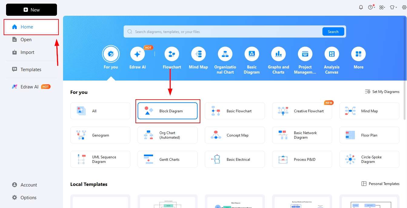
Step1 Open EdrawMax and get started
- Open EdrawMax and click the block diagram on the Home page.
- Find the block diagram section and click it.
- The empty canvas will be opened, and you will find the relevant elements.
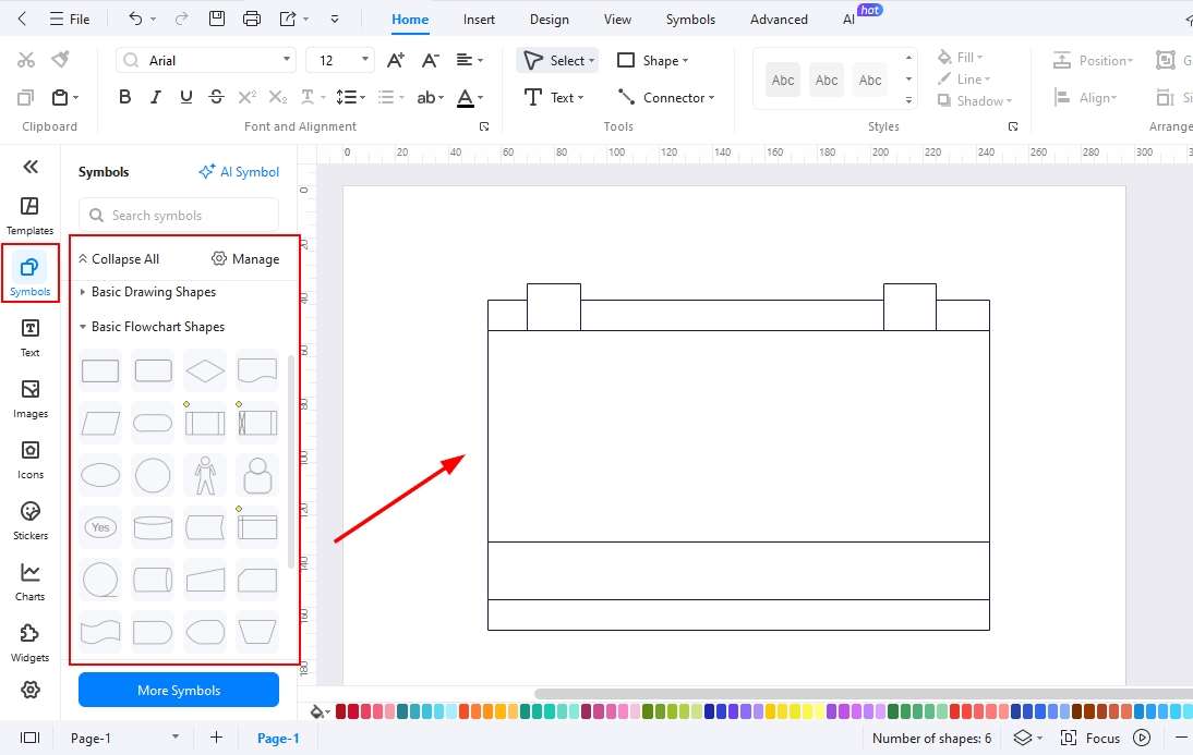
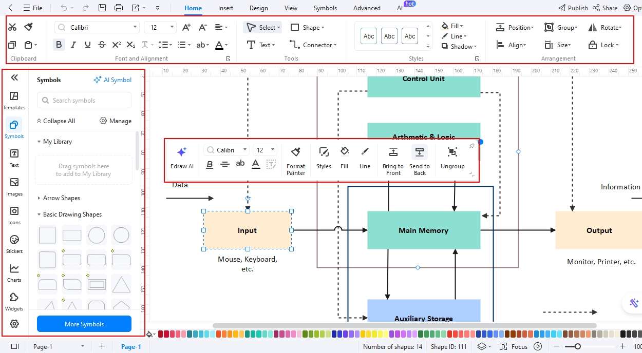
Step2 Drag and Drop Symbols and Elements on the canvas
- Go to the Symbols library.
- Search for block diagrams, and you will find all the relative shapes you need to make a block diagram.
- Click an element or drag it directly to the canvas.
Step3 Add Text for each Block
- Arrange block sizes and place them where you want them to be on the canvas.
- Double-click the block to add text for each block.
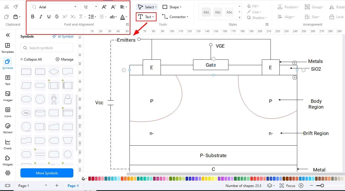
Step4 Add Relationships/ Connections
- Start adding the relationships among the blocks using the connector tool.
- If you need arrows, you can also use the symbols library to find arrows of different shapes.
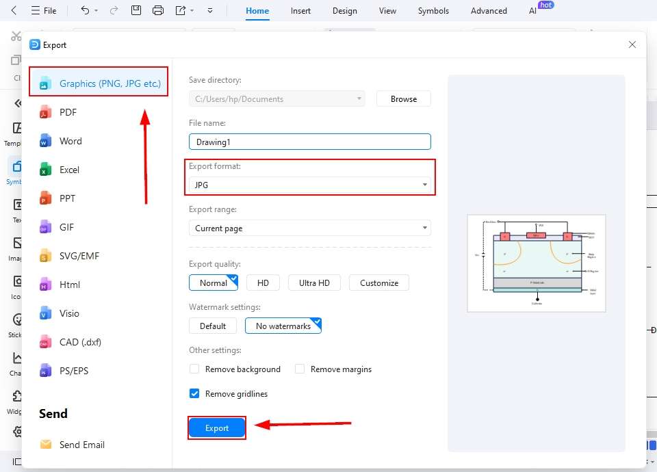
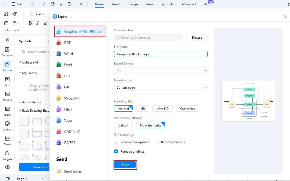
Step5 Export your Block Diagram
- Once you are finished with all the edits, you can now export your file.
- Click the export button or File in the upper left corner of the screen and choose a format.
- Set all your preferences, like image quality and zoom percentage, and click export to save the design.
Method 2: Start with an IGBT block diagram Template
EdrawMax offers a vast template library to help you get started quickly. These ready-made designs provide a strong foundation, allowing you to customize and create your own block diagrams with ease. Follow the steps below to begin designing a block diagram using one of these templates.
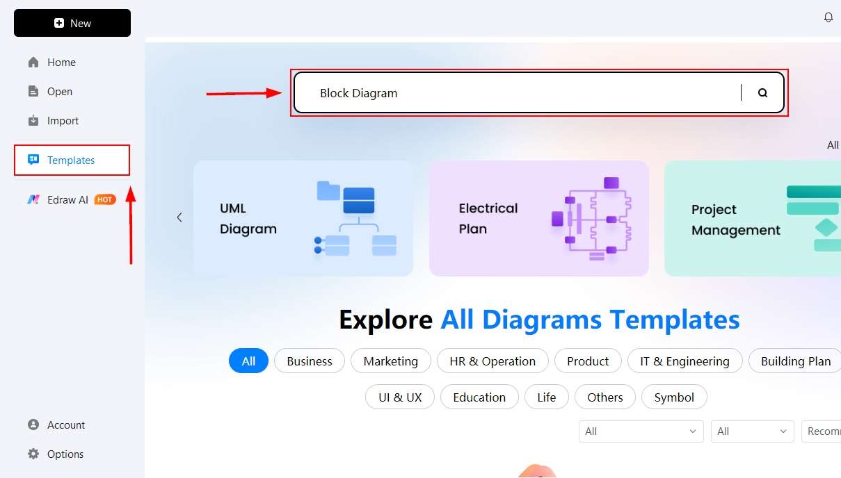
Step1 Open Templates Library
- Open EdrawMax Home Page and click templates on the left-hand side of the screen.
- Search for the block diagram templates using the search bar.
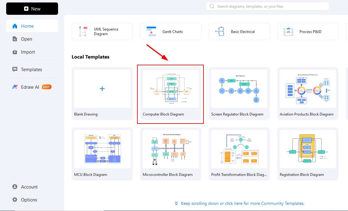
Step2 Select a Template and Click it
- Find the template from the given options and select one that is best suited for your block diagram.
- Click it to bring it onto the canvas and start editing it.
Step3 Edit the template
- Start editing the template on the canvas.
- Add or delete any shape needed.
- Use your own text by deleting the text that is already there.
- You can change colors and themes for your block diagram here.
Step4 Export your file
- Now, it is time to export your design.
- Click the file and find the export button available at the top of the menu bar.
- Please select the format in which you need your diagram and save it.
Final Thoughts
IGBTs are widely used in modern devices to deliver consistent power under applied voltage, while also controlling the amount of current flowing through a circuit. An IGBT block diagram offers learners a clear understanding of its internal functions and working principles.
With EdrawMax, you can easily create accurate and professional block diagrams for various applications, including solar systems, lighting systems, and UPS circuitry.
These diagrams not only support learning but also provide valuable insights for practical use. Start creating your own IGBT diagrams with EdrawMax to simplify complex concepts and enhance understanding.
AI Diagram Generator
Enter your prompt. Upload files if needed. Generate diagrams, charts, or slides instantly.


