


A modern warehouse handles many moving parts—from receiving goods and storing them, to picking, packing, and shipping orders to customers. Managing this complexity requires a clear understanding of how data flows through the system. That’s where an Entity-Relationship Diagram (ERD) comes in. It maps out the key elements of a warehouse—such as products, inventory, orders, and locations—and shows how they relate to each other.
A well-designed ER diagram serves as the foundation for building a reliable warehouse database. It ensures the system reflects real-world operations and aligns developers, warehouse staff, and business teams around the same structure.
This article covers the essential parts of a warehouse ERD, explains how it supports database design, and outlines the steps for implementation. You'll also see how good tools make it faster to create diagrams and collaborate with your team.
In this article
- What is an ER Diagram?
- Core Components of an ER Diagram
- Identifying Entities for a Warehouse Management System
- Defining the Relationships and Cardinality
- Examples of ER Diagram for Warehouse Management System
- How to Create a WMS ER Diagram in 5 Steps
- Best Practices of an Effective and Clear ER Diagram
- Ending Notes
- FAQ
What is an ER Diagram?
An ER diagram for warehouse management serves as a base for understanding and documenting the warehouse processes. It involves entities like staff, suppliers, goods, and the warehouse, along with their attributes and relationships. An ER diagram for warehouse management does three things particularly well:
- Clarifies data requirements. You can see what fields, keys, and constraints are required (SKU, location_id, quantity_on_hand). After this, you can create the database.
- Captures relationships and rules.
- Many-to-many relationships (products on orders)
- One-to-many (one supplier → many products)
- Dependent (weak) entities are easy to express visually.
- Guides implementation and testing. Developers and database experts use the ER model to design normalized tables. These include foreign keys and setting up indexing. Moreover, these are tested by QA teams to check their data integration constraints.
The warehouse system ER model is simple. It shows how information is stored and how it relates to key steps in database design. The database will support the picking logic, stock reconciliation, and reporting. The ER diagram has a good combination with tools like EdrawMax. It serves as a dynamic tool offering many functionalities. It contains templates, exporting capabilities, and collaboration features. This enables teams to make iterative changes. This is also dynamic to adapt to the changing needs of the data model.
Core Components of an ER Diagram
A well-established and structured warehouse entity-relationship diagram consists of various features. Below are a few of the essential elements that make up a high-level warehouse database design.
Typical Relationships
- One supplier supplies many products. Similarly, many suppliers may supply the same product.
- A warehouse contains many bin locations.
- Product stock is tracked per warehouse/location.
- PO lines associate products with orders.
- Order lines link orders to products.
- A sales order may have one or more shipments, depending on the rules.
Special Cases
- Associative Entities (e.g., OrderItem) resolve many-to-many relationships. These carry attributes like quantity and unit price.
- Weak entities are those where the primary key is made up of different attributes. This includes examples like Inventory Batch. Here, the primary key is based on both the Product and Lot numbers.
- Multi-valued attributes such as product tags are often normalized into a separate table. This table can be named ProductTag.
- Constraints and business rules (such as first-in, first-out lot selection and reserved quantities) are used in the ERD. This should be implemented in application logic or set as DB triggers.
Erasing these relations with an ERD keeps these relationships clear. It also helps in the avoidance of pitfalls in database design. A few examples can be duplicate data and ambiguous foreign keys.
Identifying Entities for a Warehouse Management System
A few of the key entities, along with their attributes, are:
- Product (SKU, Name, Description)
- Supplier (ID, Contact Info)
- Warehouse (ID, Location, Capacity)
- Inventory (Product stock at each warehouse/location)
- Location (Bin)
- Customer (ID, Address)
- PurchaseOrder
- PurchaseOrderLine (POItem)
- SalesOrder (ID, Date, Status)
- SalesOrderLine (OrderItem)
- Shipment (fulfillment details)
- Employee (staff handling operations)
Defining the Relationships and Cardinality
- Warehouse stores Product: Many-to-many, resolved by Inventory with Quantity.
- Supplier supplies Product: One-to-many.
- Customer places Order: One-to-many.
- Order contains Product: Many-to-many, resolved with OrderLine.
Examples of ER Diagram for Warehouse Management System
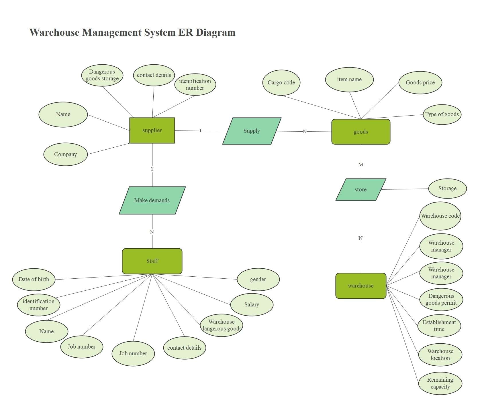
ER Diagram for Warehouse Management System
This ERD focuses on the core connections of a warehouse system. It shows how suppliers deliver goods. These items are kept in warehouses and handled by workers.
Each supplier has key details, like name, company, ID number, and contact info. Items include item name, type, price, and cargo code. Employees are connected by their roles, employee numbers, and salaries in the system. This makes work easier. Warehouses have codes, managers, a location, storage capacity & permits for hazardous materials.
The diagram shows how people, suppliers, products, and warehouses work together. They help keep warehouse processes smooth and ensure products flow well.
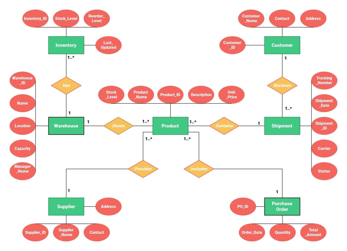
ER Diagram for Warehouse Inventory Management
This ERD focuses on how products move through a warehousing system. It represents the associations between warehouses, stock, goods, orders, customers, and manufacturers. The stock position, the reorder position, and the update history are kept at the warehouse end. Goods arrive at the warehouse from suppliers.
Then, they are packed for shipment. Customers get shipment objects with tracked IDs, dates, carriers, and statuses. The order entity orders items from suppliers and contains information such as: OrderingDate, quantity, and total cost. This data model shows how to manage inventory, supplier ties, customer orders, and shipments in warehouses.
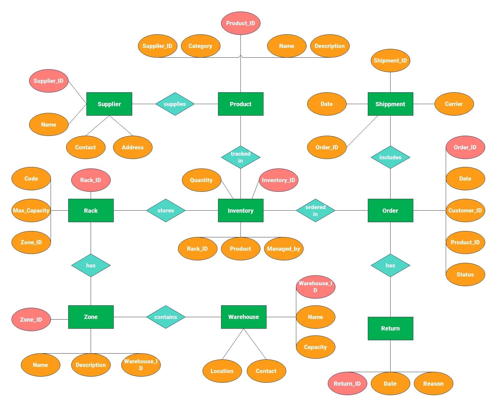
ER Diagram for Warehouse Structure
This ERD example of warehouse management can be used as a sample for the data model for your own warehouse. The area consists of several zones with racks for placing products. Manufacturers track products in stock by using the product identifier, description, category, and quantity. Orders include items and link to shipment and customer details. Returns are noted with a reason and date. Warehouses have properties such as address, size, and contact info.
This model shows not just product and supplier management, but also storage structure. This helps in monitoring and controlling stock movement effectively.
How to Create a WMS ER Diagram in 5 Steps
Applications such as EdrawMax let one create a warehouse ER diagram easily. The no-code functionality allows teams to create and share models with drag-and-drop functionality, templates, and the option to export them.
Some of the different formats accepted by EdrawMax include PNG, Visio, and SQL-like script. It also allows teamwork because the developers, DBAs, and managers can view the same ERD simultaneously.
Steps to make a warehouse management ER diagram
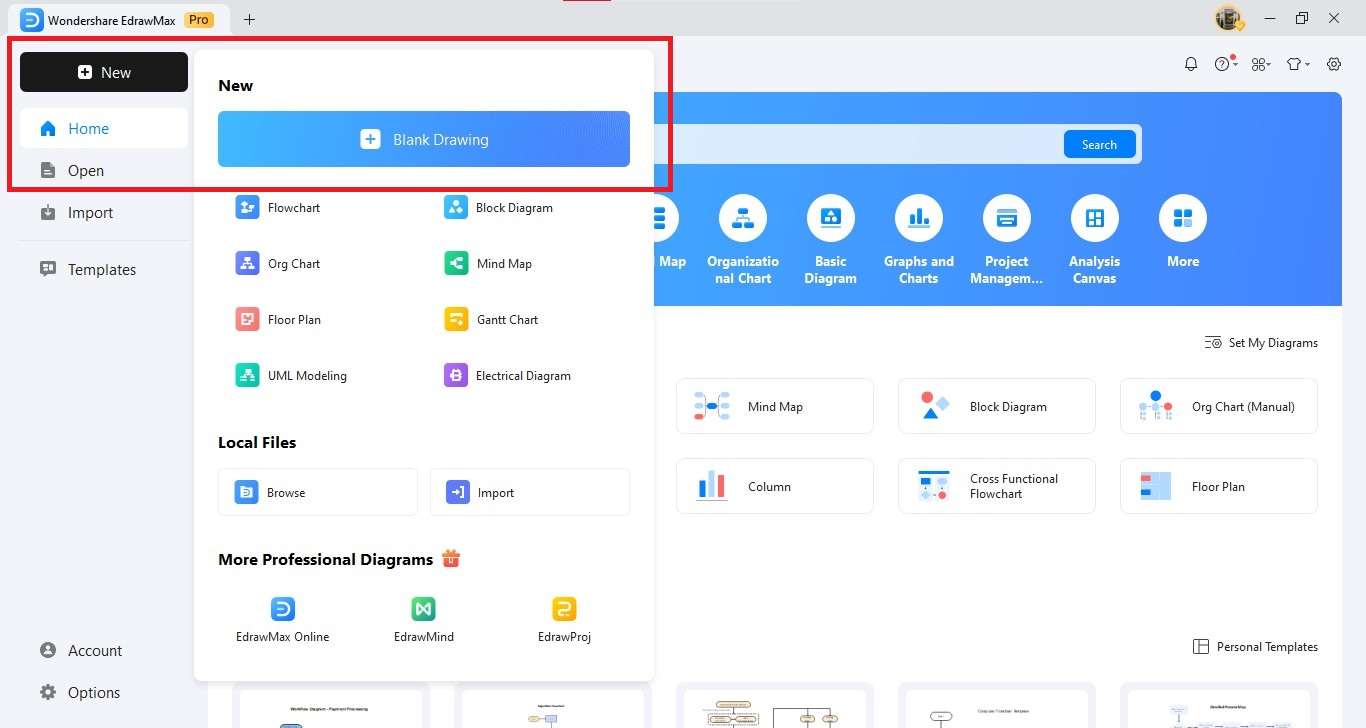
Step1 Create a New Canvas
- Open EdrawMax on your desktop.
- Go to the New section in the left panel.
- Select Blank Drawing.
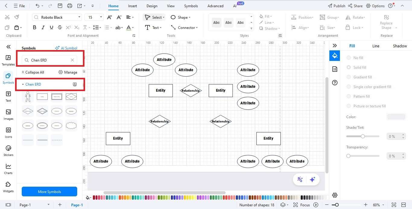
Step2 Insert ERD Symbols
- Go to the Symbol Library on the left.
- Turn on Entity-Relationship symbols.
- Drag the needed shapes onto your canvas.
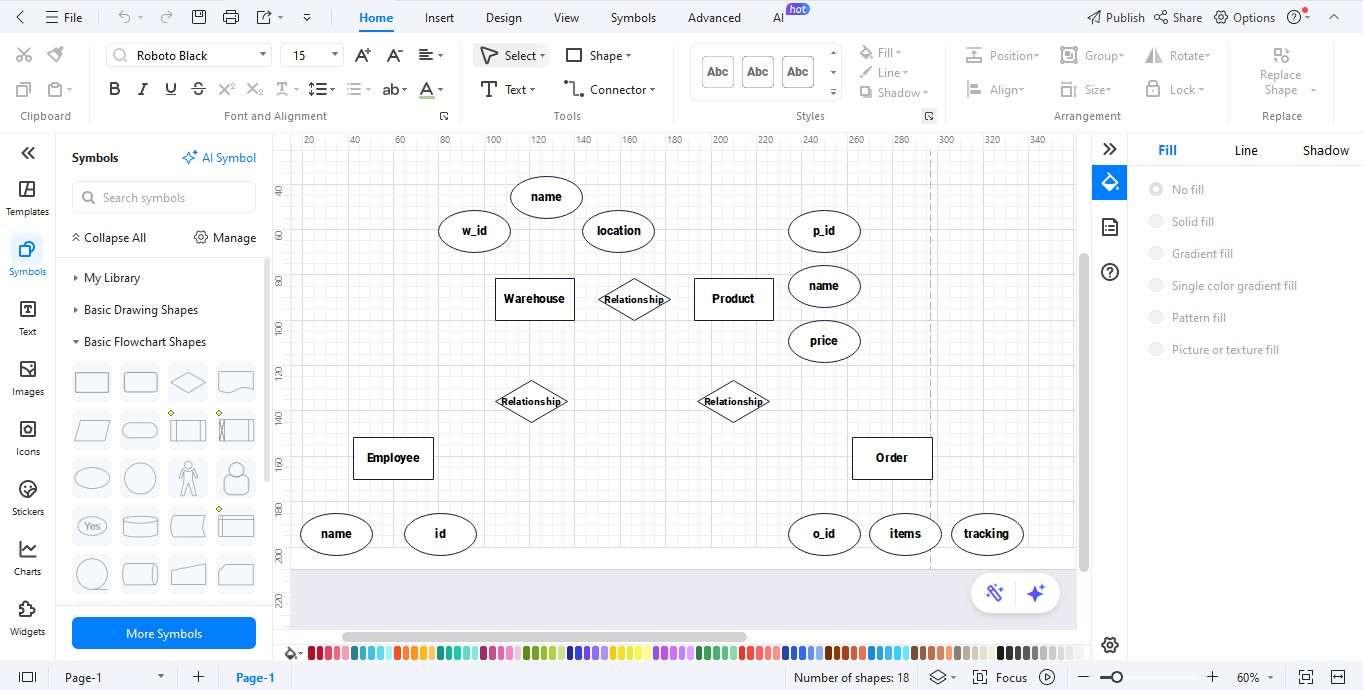
Step3 Add Entities
- Insert primary entities: Warehouse, Product, Employee, and Order.
- Arrange logically for clarity.
- Label each entity clearly.
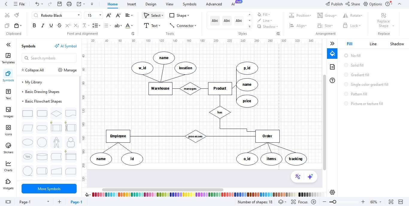
Step4 Define Relationships
- Link entities using relationship connectors.
- Examples: Warehouse manages Product, Employee processes Order.
- Ensure relationships match warehouse operations.
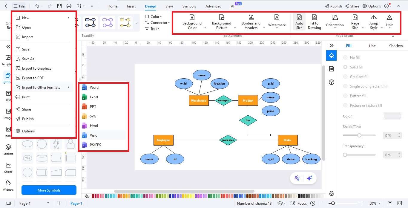
Step5 Personalize and Export
- Customize fonts, colors, and line styles.
- Use alignment tools for a clean diagram.
- Export ER diagram in JPG, PNG, PDF, Word, or SVG.
Best Practices of an Effective and Clear ER Diagram
- Use consistent entity names (e.g., Product, not products).
- Avoid redundancy; store each detail once.
- Start with core entities, then add details.
- Validate against real business logic like stock policies.
Ending Notes
Warehouse ER diagrams are essential for reliable warehouse software and database design. They translate business processes into a coherent ER model, reduce data errors, streamline integrations, and accelerate analytics. Tools like EdrawMax simplify the process and enable collaborative editing with templates and symbols.
FAQ
-
Describe a key entity in an ER diagram for a warehouse?
Product is central, but Inventory is critical because it links Product, Warehouse, and Quantity. -
Why do we need associative entities?
Many-to-many relationships (like Order and Product) need entities like OrderLine. They store extra details like quantity and price.
AI Diagram Generator
Enter your prompt. Upload files if needed. Generate diagrams, charts, or slides instantly.


