


The simplest power control circuits use MOSFETs to regulate voltage and current in DC systems. The system describes how energy moves through transistors and resistors, and loads to enable exact control of brightness and speed through pulse-width modulation. Power regulation systems achieve high efficiency because they boost system performance while reducing energy loss and extending the operational lifespan of devices that include lighting systems and motor-driven tools.
The article explains MOSFET-based control systems through detailed steps, which explain both main components and their functional principles. You’ll also find circuit examples and design tips with a guide to make a MOSFET diagram.
In this article
What is a MOSFET Controlled Power Circuit
One of the basic electronic designs is a MOSFET power control circuit. It allows precise voltage and current regulation in DC systems. It uses the switch ability of a MOSFET to regulate the quantity of current supplied to a load- an LED or a DC motor. The circuit can also control the level of light or speed in a motor by modulating the pulse width of the control signal, called pulse-width modulation (PWM), instead of converting energy into heat and wasting it.
How MOSFET works
When the MOSFET is conducting, the current is passed through the load. When it stops conducting, currents won't pass. The effective power delivered is determined by the ratio of on-time to off-time, which is known as the duty cycle. The switching is fast, and it gives a constant average output, which is equal to the required brightness or rotational speed.
The control signal is used to control the MOSFET duty cycle to regulate the average power supplied to the load. In a dimmer with LEDs, the higher the duty cycle, the brighter, whereas in a DC motor controller, the higher the rotational speed. PWM control guarantees efficient operation with low power wastage as heat.
The standard operating voltage of such circuits is between 5 V and 24 V, depending on the operating application and the load capacity. Depending on the PWM ratio, the output voltage or current is controlled, and as a result, it is possible to control the intensity of the lights or the motor torque accurately.
Benefits of using a MOSFET Controlled Power Circuit
MOSFET-based circuits in comparison with the traditional resistive control are much more efficient, compact, and reliable. They are common in lighting dimmers, motor drivers, and other power electronics in which smooth and energy-efficient operation is required.
MOSFETs are better than resistive or linear control circuits. Their high switching rate with lower loss cuts down the amount of heat, increases the use of electricity, and extends the lifetime of the equipment involved in lighting, automation, and other DC power systems.
MOSFETs are efficient compared to resistive or linear control. Their capability to transition fast with minimal heat production leads to reduced heat generation, enhanced energy consumption, and increased life of the device through lighting and automation systems.
Key Components in a Power Control Circuit
The circuit of a MOSFET power control can regulate the current and voltage flow to a load without waste of energy. It is designed in a very easy-to-use manner with a switching action to regulate the amount of power getting to the device. The combination of all parts is to control the flow of electricity and ensure a stable operation with different loads.
MOSFET (Switching Device)
The central electronic switch used in the circuit is the MOSFET. It quickly switches on and off depending on the control signal to turn the amount of power applied to the load up or down. The high switching speed and low resistance allow it to be used in control by PWM.

DC Motor
The DC motor is the load (a device that receives controlled power). The motor converts electrical energy into mechanical energy, and the control circuit affects its rotational speed. The load’s characteristics influence the required switching frequency and duty cycle.

Resistor
The circuit of the load or the gate is usually connected in series with a resistor to reduce the flow of current and stabilize its operation. It shields elements against overcurrent and provides an appropriate response.
PWM Source (Pulse-Width Modulation)
This is the control brain. It gives accurate instructions to the switch, whether to keep it on or not. It regulates the final output voltage by modulating these pulses.

Capacitor
A capacitor levels the fluctuations in the voltage and removes noise due to fast switching. It will assist in stabilizing DC output and will eliminate the flicker of LEDs or the wavy torque of motors.

Working Principle Explained
In the power-driver circuit of the MOSFET, energy is not wasted. It is regulated and timed. The MOSFET rapidly makes current, through a pulse-width modulation (PWM) signal, and the circuit can control the power that may be applied to the load, e.g., an LED or DC motor. The pulse size may be moved to the brightness or velocity in a more gradual style, and also make it efficient.
PWM Operation When the MOSFET is triggered, energy is used, and thus, the flow through the load is possible. But, in the off state, no current will flow, and the average power that can be delivered will be dependent on the duty ratio or the percentage of time that the MOSFET will be ON in each cycle. The increased duty cycle will deliver more energy, making the motor run faster or the LED brighter; the decrease is a result of a shorter ON time.
Continuous vs. Pulsed Operation The switching is fast enough to nearly make the load constant in continuous drive, useful either to provide a steady light or to allow motor rotation to be constant. When operating in a pulsed or discontinuous mode, the current momentarily goes to zero, and this will be at low duty cycles or on loads that are light.
Role of Filtering Components The capacitors and resistors reduce the jolting motion in the motors and flickering of the LEDs by averaging the PWM waveform. This ensures stability in the performance even when the switching frequency changes.
MOSFET-Controlled Power Circuit Diagram Examples
There are various types of MOSFET power control circuits, which depend on usage. The basic principle is unchanged and consists of using a PWM to control power. The design of the circuit is different depending on the characteristics of the load, the accuracy of the control, and the efficiency needs.
In this case, we shall consider two typical applications of MOSFET-based control.
Example 1: MOSFET LED Dimmer Circuit
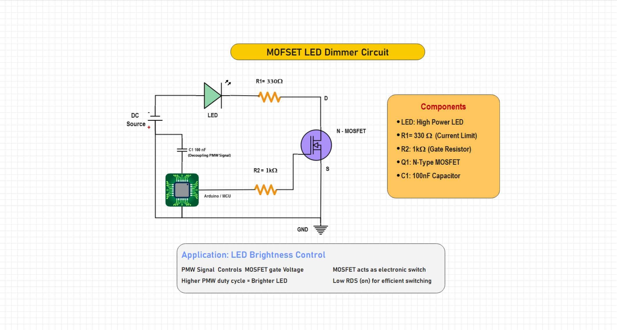
It is a typical MOSFET-induced control loop that is fed with a DC source like a 12V adapter or battery. It varies the intensity of LEDs by changing the on-time of a PWM signal driving the MOSFET. High duty cycle results in brighter light, whereas a low duty cycle results in a dimmer light. It is economical, efficient, and simple in design, which makes it suitable to use as a form of lighting.
A circuit to show an LED dimmer. In this circuit, a MOSFET is used as a PWM-controlled switch. The microcontroller responds to the gate voltage of the MOSFET to change the brightness of the LED by changing the duty cycle. A capacitor is used to smooth the signal, and resistors are used to limit current and protect gates, which provides a highly efficient method of brightness control to an LED used in an embedded lighting system.
Example 2: MOSFET DC Motor Speed Controller
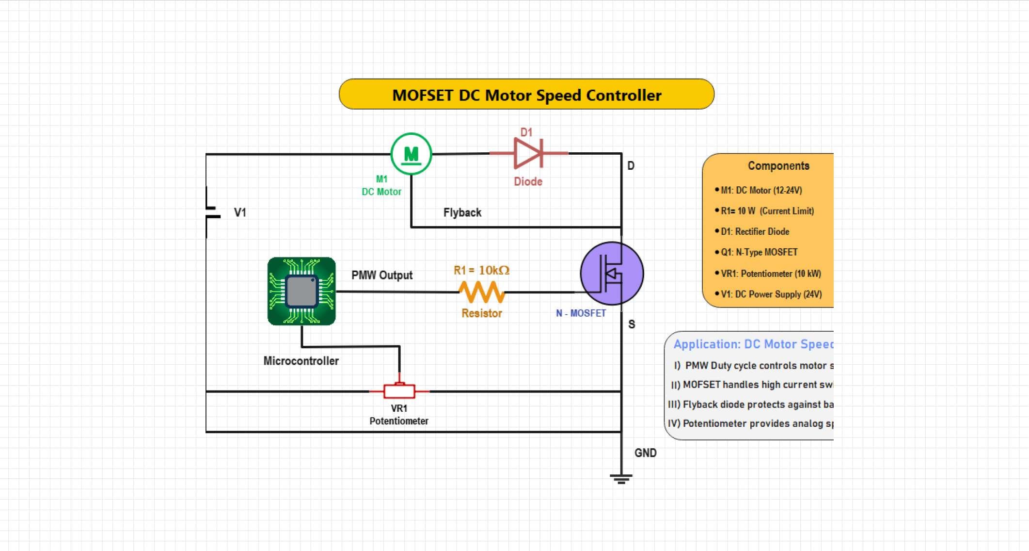
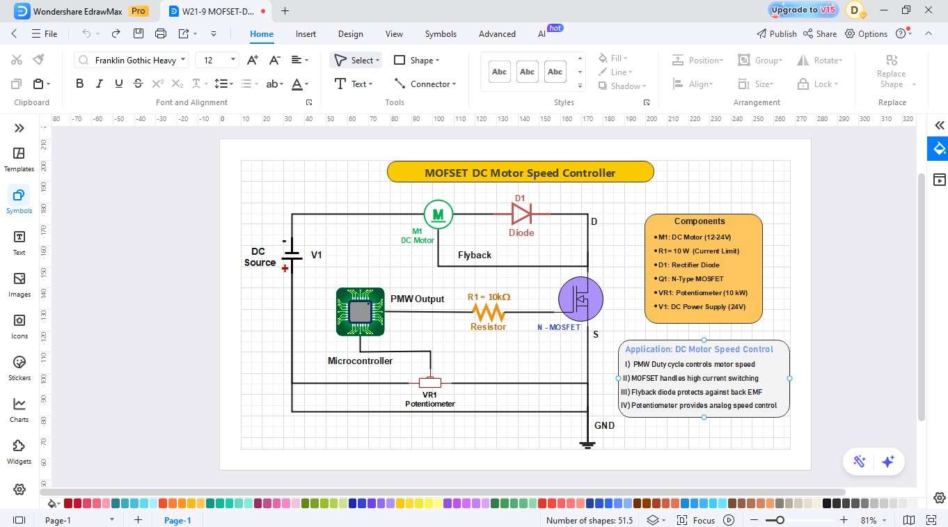
This circuit is an adaptation of the rotational speed of a DC motor using a PWM signal to control the MOSFET. The duty cycle varies to provide the average voltage required by the motor to give a smooth acceleration or deceleration. The design allows for the efficient use of power, less heat generation, and accurate control of the motor in fans, toys, and automation systems.
The circuit represents a PWM-based DC motor speed controller with an N-channel MOSFET. The microcontroller sends the PWM signal to change the motor speed, and manual control is done with the potentiometer, setting the duty cycle. A flyback diode prevents the back EMF and provides the seamless operation and safe usage of motors in the embedded and automation systems.
How to Draw a MOSFET Circuit Diagram in EdrawMax
It might appear difficult to draw a power control circuit of MOSFET, we can easily create one with EdrawMax and its prepared circuit diagram features.
The drag and drop interface enables you to quickly add MOSFETs, PWM sources, resistors, capacitors, and loads, then all the elements interconnect and style to build your own professional LED dimmer or motor controller circuit diagram within only minutes. Just follow these steps:
Step1 Make a New Project
Open EdrawMax. Click New on the left panel. Select New Blank File to begin with a blank canvas.

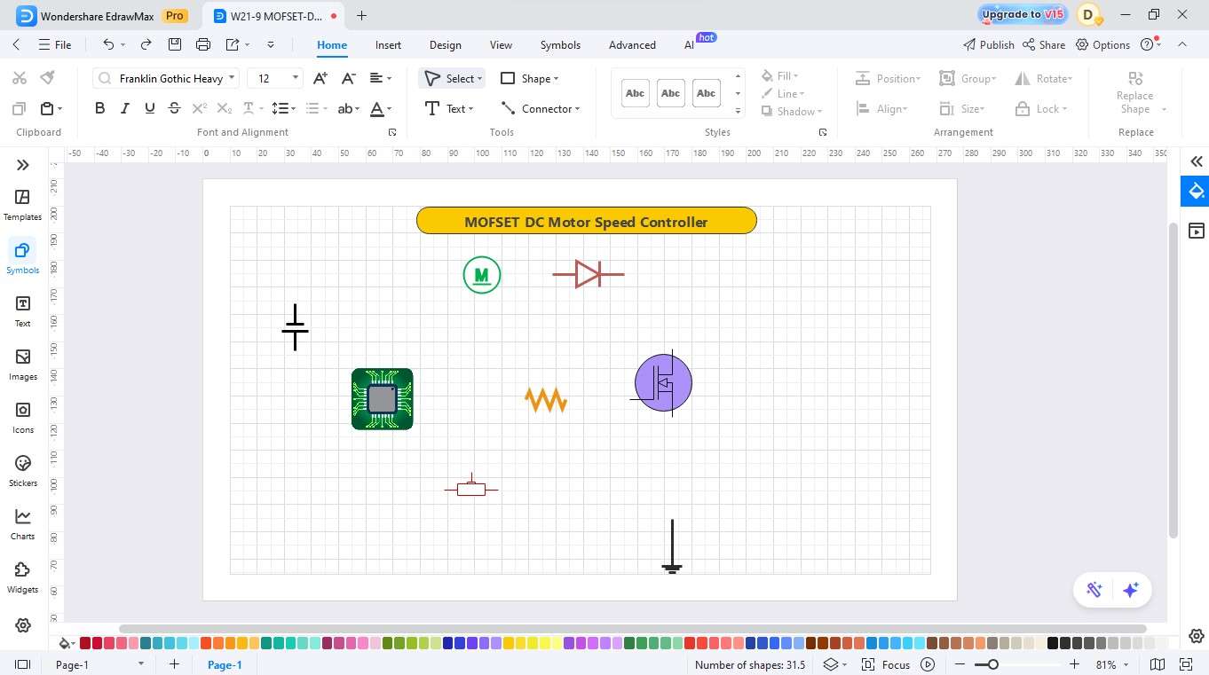
Step2 Select Electronic Symbol Libraries
Select the left toolbar of Symbols or More Symbols.
Click on More Shapes. In the Shape Library, search “electrical”
Choice Basic Electrical symbols, Electrical Audio, as well as Electrical Instruments.

Step3 Trace the Power and Add Components
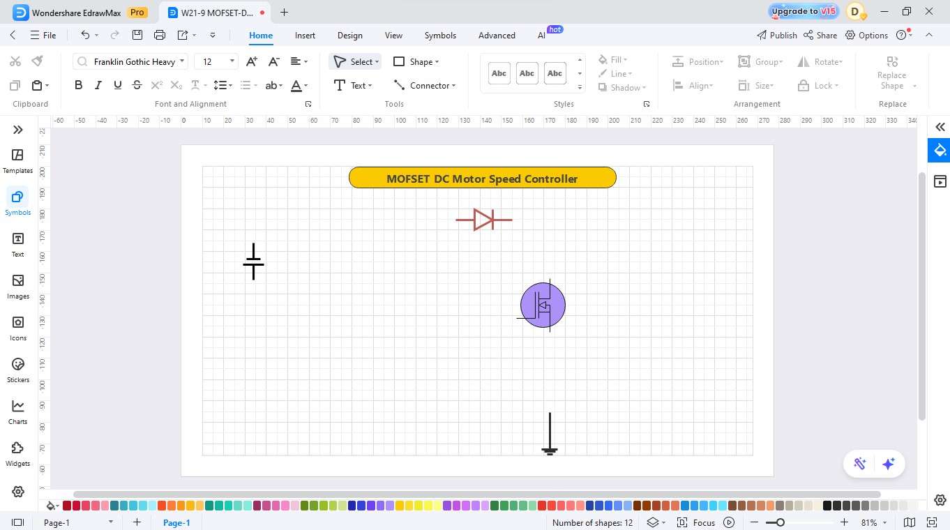
Pick a DC power source and drag it to the canvas.
Place a diode and MOSFET/Transistor next to it, which is then used to show the switching device that controls the flow of energy.
Step4 Add Microcontroller and Potentiometer
- Include a microcontroller that is programmed to switch instructions.
- At this point, the ground symbol, a resistor, and a potentiometer are dragged into the circuit.
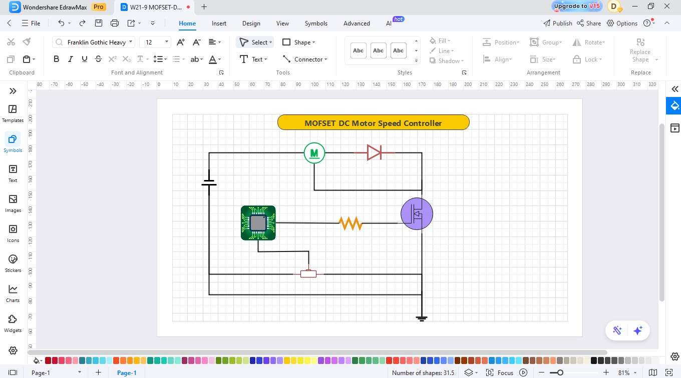
Step5 Add the Load and the Capacitor of the Output
- Connect all the parts with proper wiring connections.
- Ground the rest of the circuit. Improve the circuit by extending the wire to ground.
Step6 Label the Components and Customize
- The system contains three essential components, which are the MOSFET, the Diode, and the Inductor.
- Change the colors of the desired element.
- Notes should be written on the components and description.
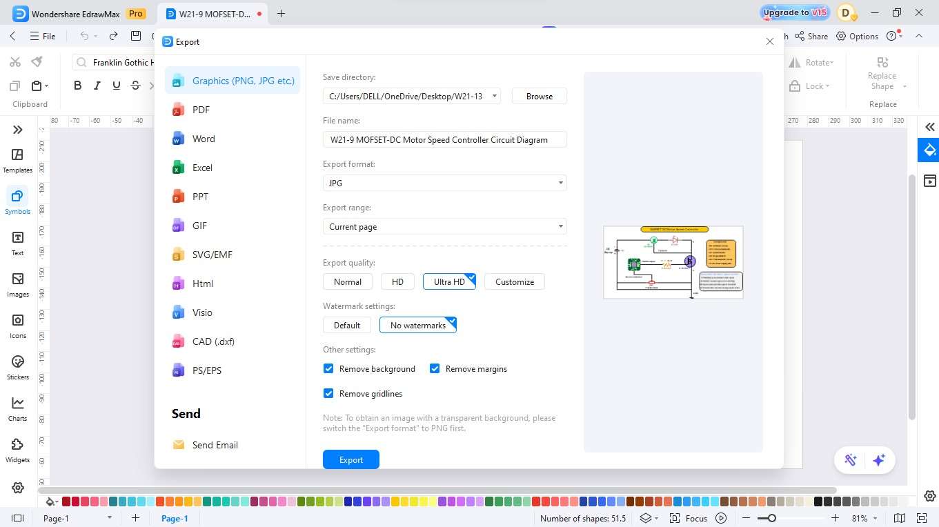
Step7 Export
- Complete the chart to make certain that all indents and spacings are clear and consistent.
- Once completed, save your design.
- The process demands you to choose a file format for your drawing between JPG, PNG, SVG, and PDF.
EdrawMax, an All-in-one diagram tool
EdrawMax is a universal diagramming tool that allows users to create MOSFET control networks without any problems, even without prior knowledge. Its drag-and-drop interface and huge component libraries enable users to make professional LED dimmer or even motor controller circuit boards and timer designs without difficulties.
Key Features
- Large symbol libraries in MOSFET, PWM sources, loads, and other elements of the circuit.
- Clean layout, Smart Connection drag and drop editor.
- Online teamwork and safe savings.
- The ability to customize readymade templates to accelerate circuit design.
- The procedure requires you to select from JPG, PNG, SVG, and PDF file formats for your drawing.
Best Practices to Make an Accurate Design
A properly designed MOSFET controlling power circuit will guarantee a smooth, high-efficiency, and reliable operation over time. Adequately careful choice of components, behaviour of switching, as well as protection techniques can prevent overheating, loss of power, or unintended automatic circuit breakdown. To design safe and stable designs, you should follow the following tips:
Choose an Appropriate MOSFET and Parts
Select a MOSFET with an appropriate current and voltage value for your load. Carefully use resistors and capacitors of the correct value to ensure that the PWM signal is not trying to stabilize and therefore reduces electrical noise or flicker.
Control Frequency of Switching and Heat
Increased switching frequency provides a smaller adjustment step but is more heat dissipative. Frequency should be adjusted to achieve efficiency, and thermal management should be done with suitable heat sinks or copper areas on the PCB.
Noise and Burst protection
Add a snubber circuit (transient voltage suppressor), a Transient voltage suppressor (TVS) diode. Across the power lines, filtering capacitors can also diminish EMI, as well as result in the even functioning of LEDs or motors.
Conclusion
The next diagram of a power control circuit based on MOSFET will allow you to know and develop effective LED dimmers and motor speed controllers. It reveals the interaction of all its parts to furnish a balance of power smoothly and reliably.
Using EdrawMax, professional circuit diagrams can be easily drawn using its drag-and-drop development features and built-in symbol libraries, and thus, precise design is easy even for novice users.
AI Diagram Generator
Enter your prompt. Upload files if needed. Generate diagrams, charts, or slides instantly.


