


Software teams find it difficult to communicate system design to non-technical individuals. Mistakes may lead to time wastage and costly mistakes. Visual diagrams provide a common understanding of how the system operates to everybody. This makes it easier to collaborate and make quicker decisions.
C4 model diagrams are useful here. They introduce software architecture in four levels: Context, Container, Component, and Code. The levels allow a deep dive into the components of a system. Both developers and stakeholders can view the right detail without confusion and overload of technical information.
This article will teach you definitions, main concepts, symbols, actual applications, and processes to design C4 model diagrams in EdrawMax.
In this article
What is a C4 Model Diagram?
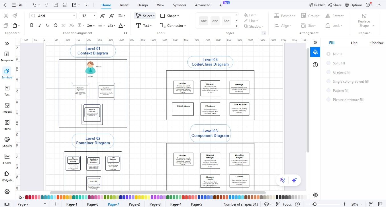
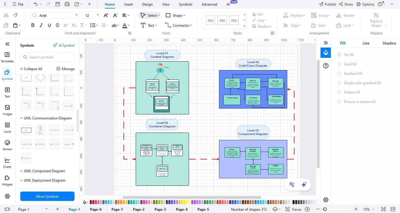
One method of presenting software architecture in layers is by use of a C4 model diagram. It assists teams and stakeholders in understanding how a system functions, both in a broad perspective and in finer detail of the code.
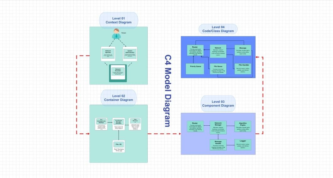
C4 derives its name from its four levels: Context, Container, Component, and Code. One level provides a varying degree of detail, such as a camera zoom-in.
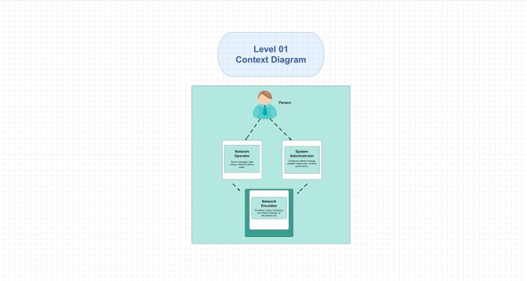
Context Diagram
It demonstrates the large-scale picture. It puts an emphasis on the interactions between the system and people and other systems. As an example, a banking application is an online banking application that links to users and payment gateways.
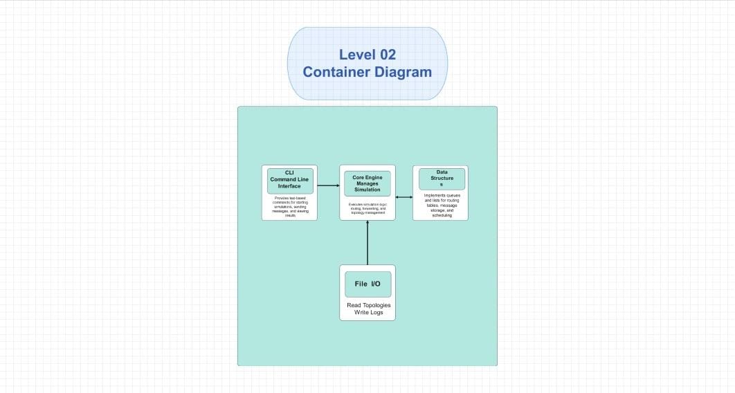
Container Diagram
It is a step further. It depicts key elements like web applications, mobile applications, or databases. This aids teams in viewing the manner in which the system is divided into large sections.
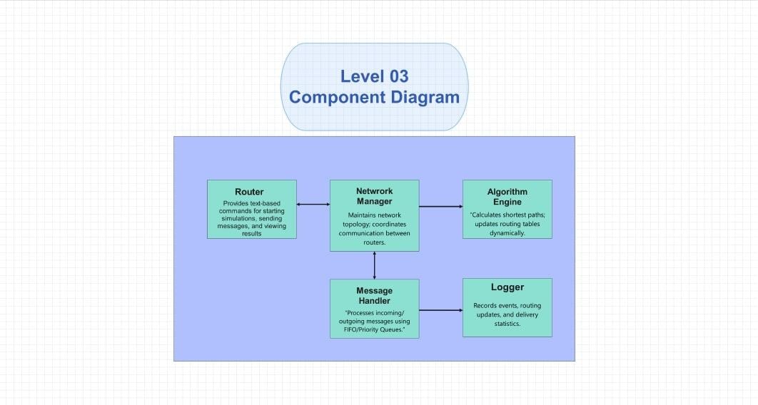
Component Diagram
It describes the activity within each container. It divides things into smaller modules, APIs, or services.
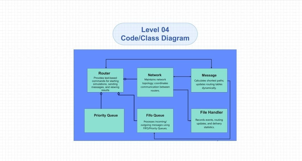
Code Diagram
The richest view is Code Diagram. It connects with actual classes or functions within the codebase, providing developers with a precise technical understanding.
C4 model diagrams are intended to simplify complex systems. Through the various levels, all the people, including the managers and engineers, know how the software is constructed and works.
Basic Concepts of C4 Model Diagrams
The C4 model diagrams are constructed with simple yet effective building blocks. Teams have a definite method of explaining how software systems operate in each block. Developers and stakeholders can easily identify who is using the system, who it is connected to, and how it is organised internally by disaggregating a system into parts.
People– actors/users
People are the first building block. These are the users or actors who interrelate with the system. They may be customers, employees, or even other systems that can be considered as users. Being demonstrative assists in making clear who is benefiting from the system and who relies on the system.
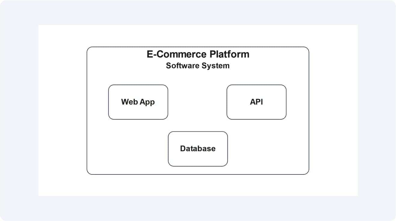
Software System
Next is Software Systems. These are internal and external systems your team constructs, such as payment gateways or third-party APIs. Mapping systems make sure that everybody sees the model of interactions.
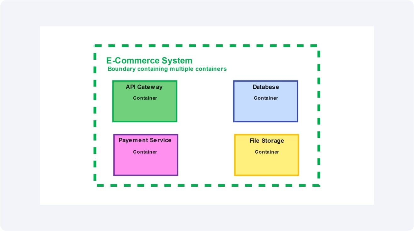
Container
Containers are within a system. They are web services or microservices, databases, or applications. The key technical components that operate the system are defined by containers.
Component
Lastly, components are within containers. They decompose containers into smaller units, e.g., modules, APIs, or libraries. This tier plays a vital role in the developers knowing the structure and responsibilities.
These sections, when combined, provide a clear picture of the system. You are able to see who utilizes it, what systems are affected, and how tasks are managed in stages.
The Symbols in C4 Model Diagrams
C4 model diagrams use symbols since they make the design less complicated and easier to understand. Every component has a typical shape, and thus teams can soon know who is utilizing the system, the flow of data, and where important components are located.
People Symbol
The first symbol is People. These are represented in terms of stick figures or plain user icons. They represent actors such as customers, admins, or staff who interact with the system.
Software Systems Symbol
Next are Software Systems. These appear as large boxes. They may be internal and constructed by the team, or external, like a payment gateway. They are joined with arrows indicating the direction in which data or actions travel between systems.
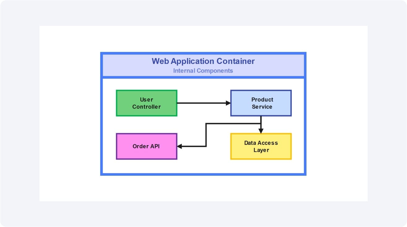
Containers Symbol
The third major symbol is containers. They are miniature blocks within a system box. Each block can denote either an app, a database, or a microservice. They demonstrate how the system is divided into working units.
Components Symbol
Components are found in containers. These are smaller modules, e.g., modules or APIs. They are seen in the form of small rectangles or blocks in a container. They describe in detail the way features are constructed together.
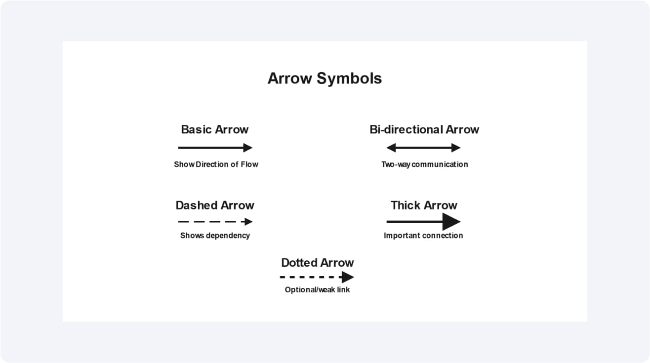
Arrows Symbol
The symbols also include very important arrows. They model the information, command, or dependency flow among people, systems, containers, and components.
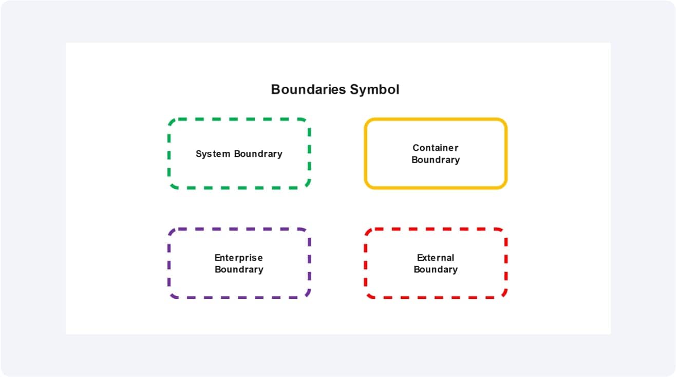
Boundaries Symbol
Boundaries are used to delimit the systems or containers, to maintain elements together.
With these few notations, a C4 model diagram remains understandable. It enables technical and non-technical individuals to look at the same picture easily.
Use Cases of C4 Model Diagrams
The C4 model diagrams are practical, as they simplify software architecture to both the teams and the stakeholders. They aid in the lessening of confusion and accelerated decision-making.
Team communication is one of the applications. The same system view can be viewed by developers, testers, and managers. This facilitates the working together process and minimizes errors.
They contribute to the agile documentation as well. The diagrams are visual notes instead of long documents that remain simple to update as systems expand.
Another good use is onboarding new members. A plain context or container diagram is useful in enabling new developers to learn the system quickly.
They also play a role in the planning of the system. Before any code is written, teams can map features, check dependencies, and plan upgrades.
And finally, C4 diagrams facilitate compliance and audits. Detailed illustrations are evidence that systems have rules and security practices. Software such as EdrawMax simplifies this process and allows templates with export options.
How to Draw a C4 Model Diagram in EdrawMax
A C4 model diagram can appear to be complicated to design, yet EdrawMax simplifies it. You can build professional diagrams step by step with its ready libraries and drag-and-drop. These are steps to construct your own.
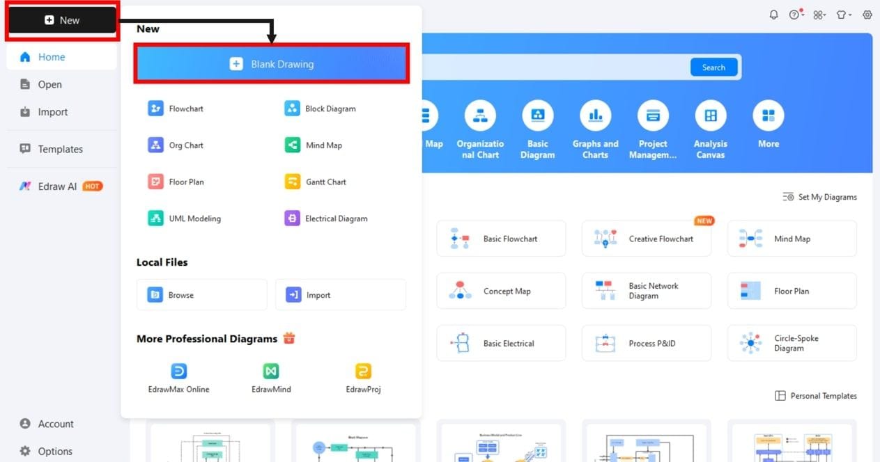
Step1 Create a New Project
- Open Wondershare EdrawMax.
- Click New on the left panel.
- To open a new canvas, select Blank Drawing.
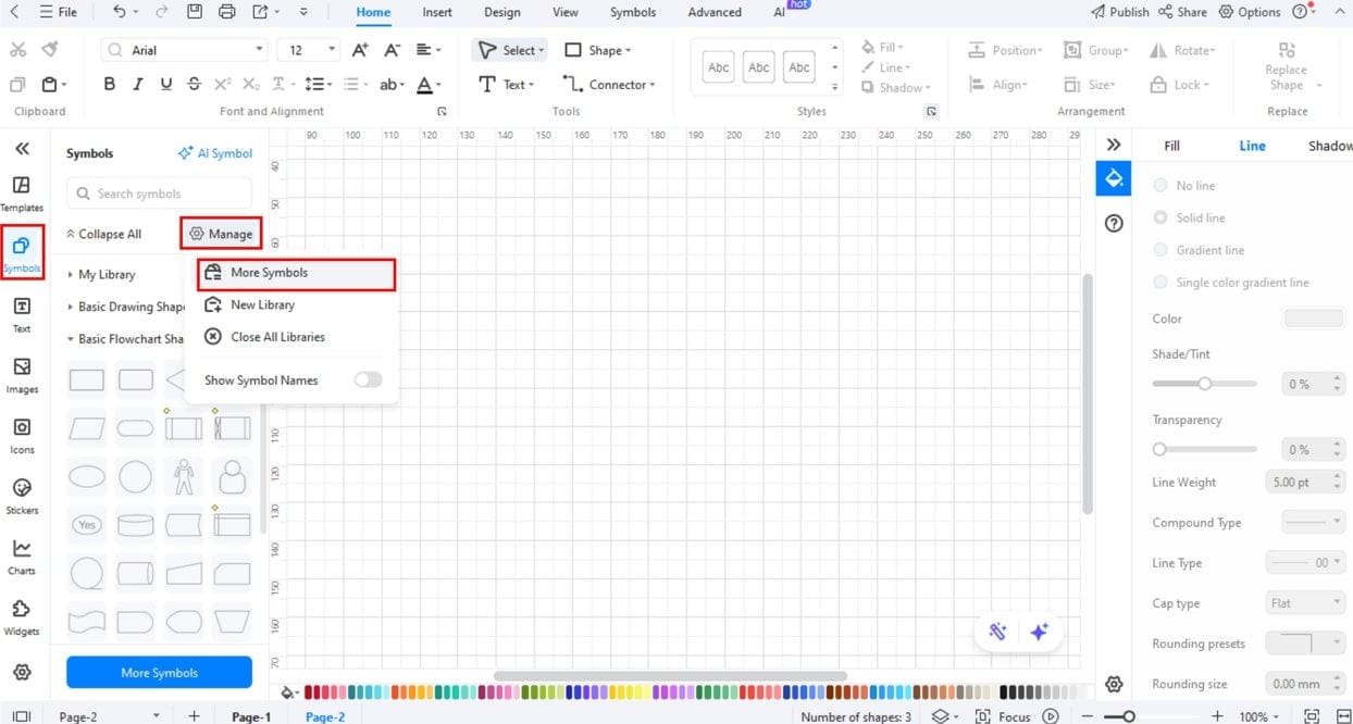
Step2 Enable Shape Libraries
- On the left bar, click Symbols or More Symbols.
- Click on Manage, Add More Symbols.
- Turn on such libraries as Software, UML, or Architecture.
Step3 Add Software Systems
- Drag a big System box per major system.
- Name internal systems and external systems (e.g., Payment Gateway).
- External systems that are evidently outside of the group boundary.
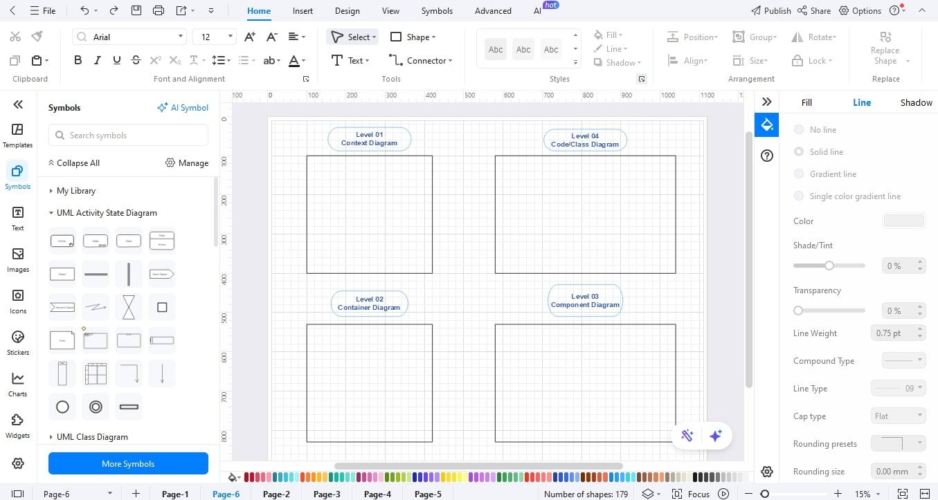
Step4 Add Containers
- Container blocks (Web App, DB, Service) can be added inside a system box.
- Label each container with its purpose (e.g., Web App, Database).
- Store containers in such a way that related containers are close to one another.
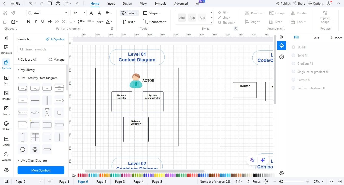
Step5 Insert People (Actors)
- Drag a Person icon in the library.
- Name it (e.g., Customer, Admin, Operator).
- Put actors on the outside of a system.
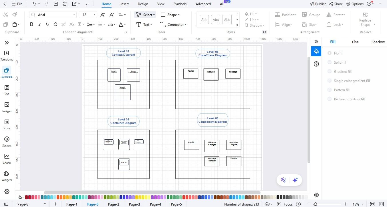
Step6 Insert Components
- Take a container and put small component blocks.
- Name elements such as API Layer, Order Module, and Login Service.
- Include a brief note of accountability to every element where necessary.
Step7 Linking with Arrows and Flows.
- Draw an arrow between people, systems, containers, and components using the connector tool.
- Name each arrow with a concise flow name (e.g., Data Query, Login Request).
- Sync calls are taken with solid arrows, and the asynchronous or events are with dashed arrows.
Step8 Style, Review, and Export
- Make things even and use the same colors and fonts.
- Include a diagram legend, notes, and title.
- Click export to share the diagram in JPG, PNG, PDF, or Word.
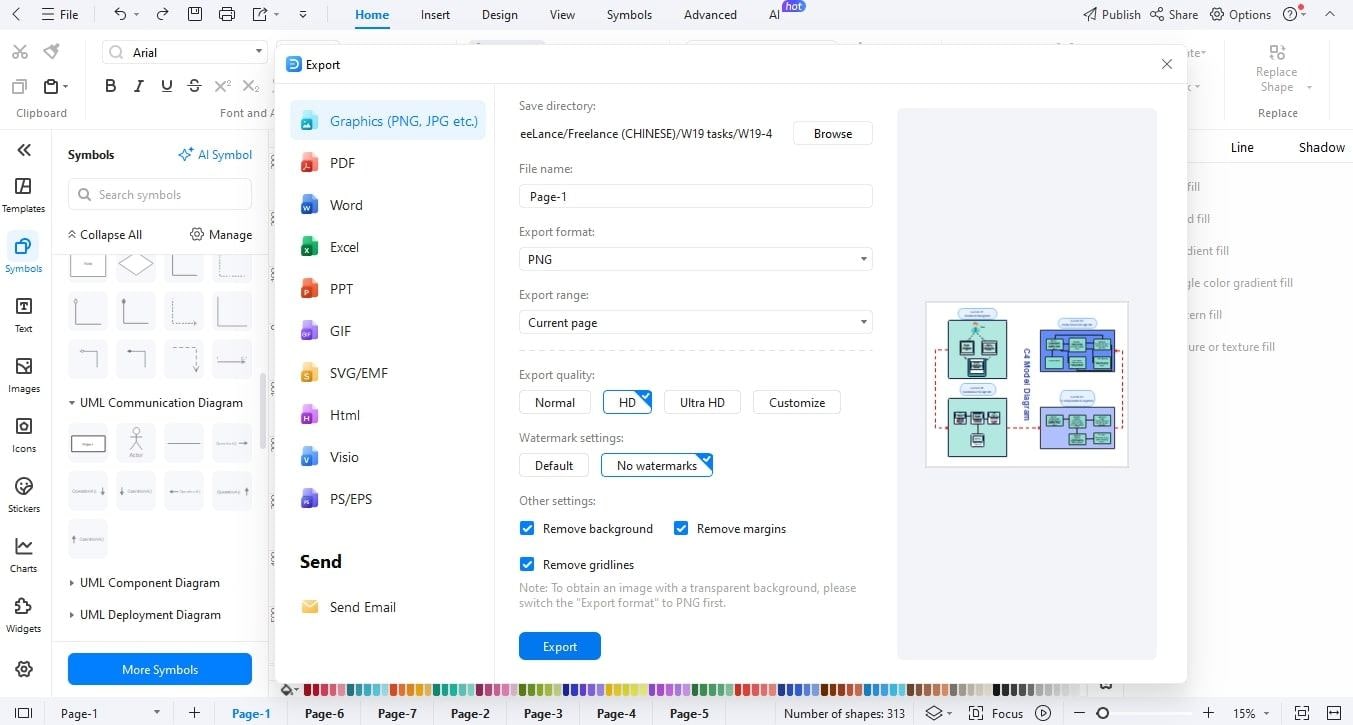
It is possible to use these steps to create structured C4 model drawings without getting confused. EdrawMax simplifies all processes, such as setting up and exporting, which is why it is a fantastic tool to have in case a group needs clear and professional diagrams to plan and communicate.
Conclusion
C4 model diagrams add order and sanity to software architecture. They assist teams in viewing systems across levels, enhance communication with stakeholders, and lead more intelligent planning. These diagrams simplify the understanding of complexity and facilitate the ease of cooperation by dividing the diagram into distinguishable layers.
The C4 diagrams with EdrawMax are easy and effective to create. Professional diagrams are easy to design because they have pre-made templates, drag and drop software, and can be exported. Start to draw your own C4 model diagrams today and transform the way in which you design software systems.
AI Diagram Generator
Enter your prompt. Upload files if needed. Generate diagrams, charts, or slides instantly.


