


The circuit diagram of a Silicon Controlled Rectifier assists in visualizing the way in which this type of semiconductor device manages and directs electric current in an electric circuit. It is also common in power control systems, e.g., dimmers of light lamps, speed controllers of motors, and voltage regulators.
Simply, an SCR is a switch that is on or off in response to the applied control signal to the gate terminal. This article shall describe how it works, its structure, and practical applications.
In this article
- What is a SCR Power Control Circuit
- Key Components in an SCR Control Circuit
- SCR Working Principle Explained
- SCR Power Control Circuit Diagram Examples
- How to Draw an SCR Power Control Circuit Diagram in EdrawMax
- Create a Circuit Diagram Online Now
- Best Practices for Creating Accurate Designs
- Conclusion
What is a SCR Power Control Circuit
An SCR power control circuit is a DC or AC regulator that carefully regulates power output to a load. It operates with a Silicon Controlled Rectifier as the primary switching element to provide control of the flow of current depending upon the firing angle of the gate signal. The circuit causes voltage and current to be adjusted as effectively as possible to the desired value by deferring the onset point within every AC cycle, or by varying the conduction period in DC systems.
SCR is a programmable switch; it is off until a pulse is sent to the gate, and when this is done, it conducts while the supply voltage is below zero or until the circuit is reset. This controlled conduction makes it possible to control the brightness of the lamps properly or the rate of charging a battery.
The phase control and the gate trigger signal are a mere network of resistors, capacitors, and diodes. These components control the activation of the SCR, meaning that the level of energy delivered to the load at any given cycle is determined by these components.
The Firing circuit varies the SCR triggering angle to control the output power. Phase control determines the period of conduction in an AC system, and pulse control determines the charging current in a DC system. Common input is between 110 V and 230 V AC, which is used in lamp dimmers, and 6 V to 24 V DC, which is used in charging batteries. The SCR control has a high efficiency, a smooth control, and a long life of the component, thus it fits in domestic or industrial power cases.
Key Components in an SCR Control Circuit
A power control circuit, which is an SCR circuit, controls the current to a load by controlled switching. It is a straightforward but efficient design and is based on the elements that are used to regulate the firing angle, the conduction period, and the total power output.
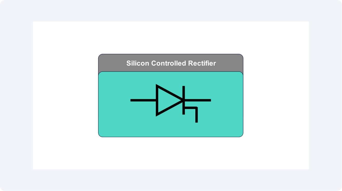
SCR (Silicon Controlled Rectifier)
The main switching circuit in the circuit is the SCR. It is a programmable diode that will only allow current to pass when a gate pulse is detected. When it is switched on, it is turned off only after the current has decreased to less than a holding level, making it possible to control the AC or DC power away to a specific level with some degree of precision.
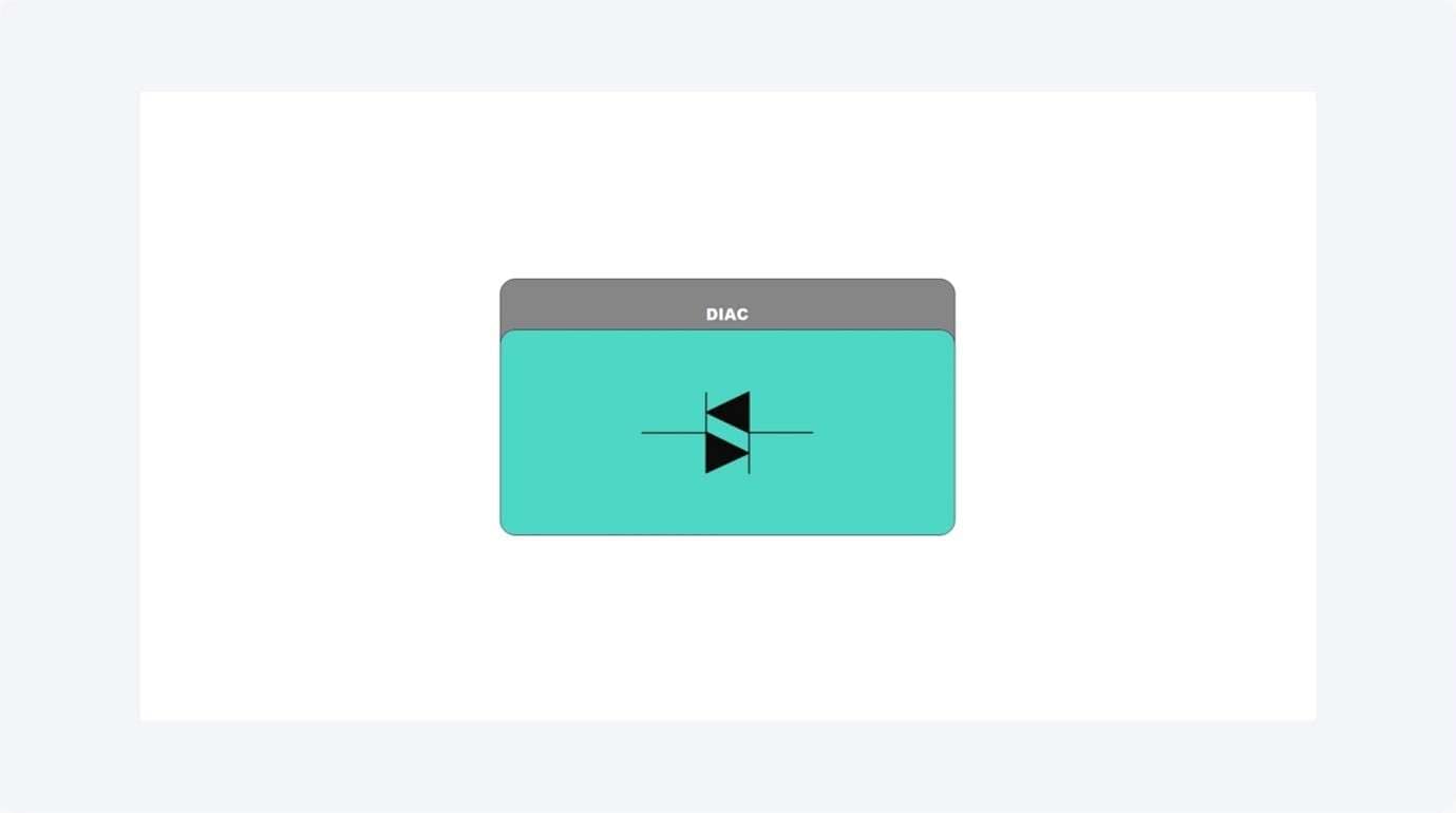
DIAC (Triggering Device)
In AC circuits, e.g., lamp dimmers, a DIAC is frequently employed to give a sharp triggering pulse at the SCR gate. It guarantees predictable firing at a particular voltage, thereby leading to better brightness control and better reduction of flicker.
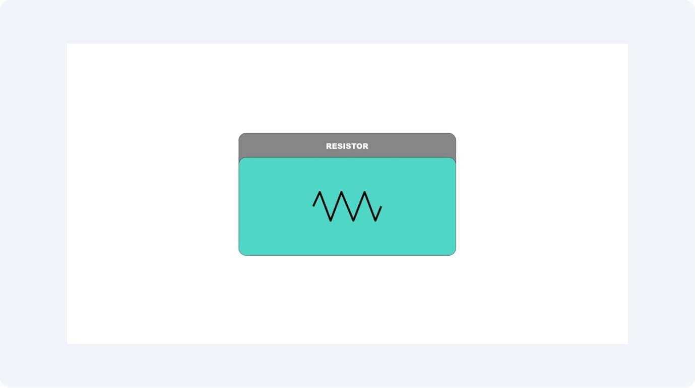
Resistor
The current and the voltage across the load and the SCR gate are regulated by resistors. They result in the rate at which the timing capacitor is charged and also aid in determining the phase angle, such that there are stable triggering and safe currents across the SCR.
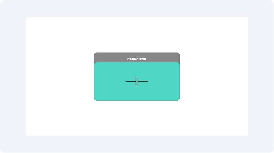
Capacitor
The Capacitor is a component of the RC network that dictates when the gate trigger pulse is conducted. When it is charging and discharging with every AC cycle, it stretches or shortens the firing angle of the SCR.
Potentiometer
The potentiometer enables one to change the firing angle or time interval manually. The user can also control the time at which the SCR should be fired by changing its resistance, and this way can alter the lamp brightness, or the rate at which a battery is charged.
Working Principle Explained
Power is controlled by an SCR-based power control using the timing when the SCR conducts in any given AC or DC cycle. When the SCR does not get a gate trigger pulse, it is held in the off position. When triggered, it is then allowed to conduct current to a load until the current returns to zero on its own or is interrupted. By controlling the time when this trigger applies, a sharp control can be achieved on the average power delivered to the load.
Phase Control Operation
The SCR is triggered at different positions in each half-cycle of the AC waveform in AC applications like lamp dimmers. An early firing of the SCR enables passing of more current to the light, causing brighter light, whereas a late firing causes the conduction time to be shorter and the light to be less bright. This type of conduction control delay is referred to as phase angle control.
DC Pulse Control
The SCR in DC circuits of battery chargers receives trigger pulses, which determine the amount of average current that reaches the battery. The charging speed depends on the duration of the pulses because shorter pulses restrict charging speed, but longer pulses enable faster charging. The system provides fast battery charging while protecting the battery from dangerous high current levels.
Role of the RC Network
A resistor-capacitor (RC) timing network controls the time delay of a gate trigger pulse. The phase angle between the resistor and the capacitor charging process initiates the DIAC to trigger the SCR. Users can control this timing and hence the amount of power supplied to the load by changing the potentiometer.
The control SCR-based is highly efficient, features a smooth change in the power, along with longer desktop life since minimum resistive losses occur, and the current management is very precise.
SCR Power Control Circuit Diagram Examples
SCR power control circuits are available in different configurations depending on their intended application. The basic operation of current control through SCR firing angle adjustment stays constant, but the circuit design changes based on the application, between AC dimming and DC charging, and other power regulation needs. The following section presents two typical examples that illustrate these applications.
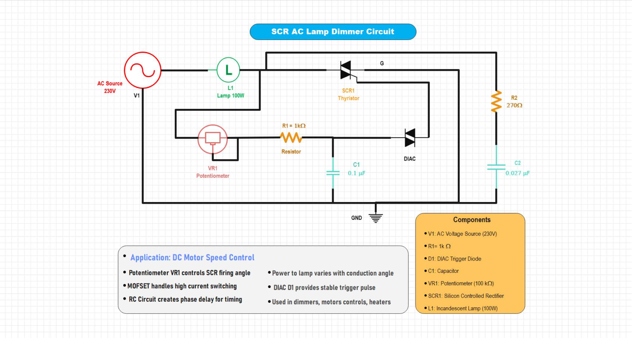
Example 1: SCR AC Lamp Dimmer Circuit
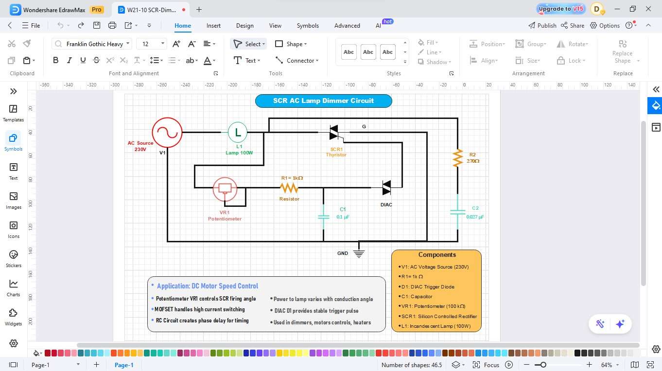
This circuit demonstrates how an SCR can control the brightness of an AC lamp. The firing angle of the SCR is adjusted using a resistor–capacitor (RC) network and a DIAC, which determines when the SCR conducts in each AC cycle. The triggering point delay allows only part of the AC waveform to reach the lamp, which decreases brightness without any loss of energy. It is a simple, reliable, and low-cost dimming solution widely used in household lighting controls.
This circuit demonstrates an SCR-based AC lamp dimmer in which a potentiometer controls the SCR's firing angle via an RC network. The DIAC provides a stable trigger pulse, adjusting the lamp's brightness by varying conduction time. It serves as a simple phase-control dimmer commonly used for lamps, heaters, and motor speed regulation.
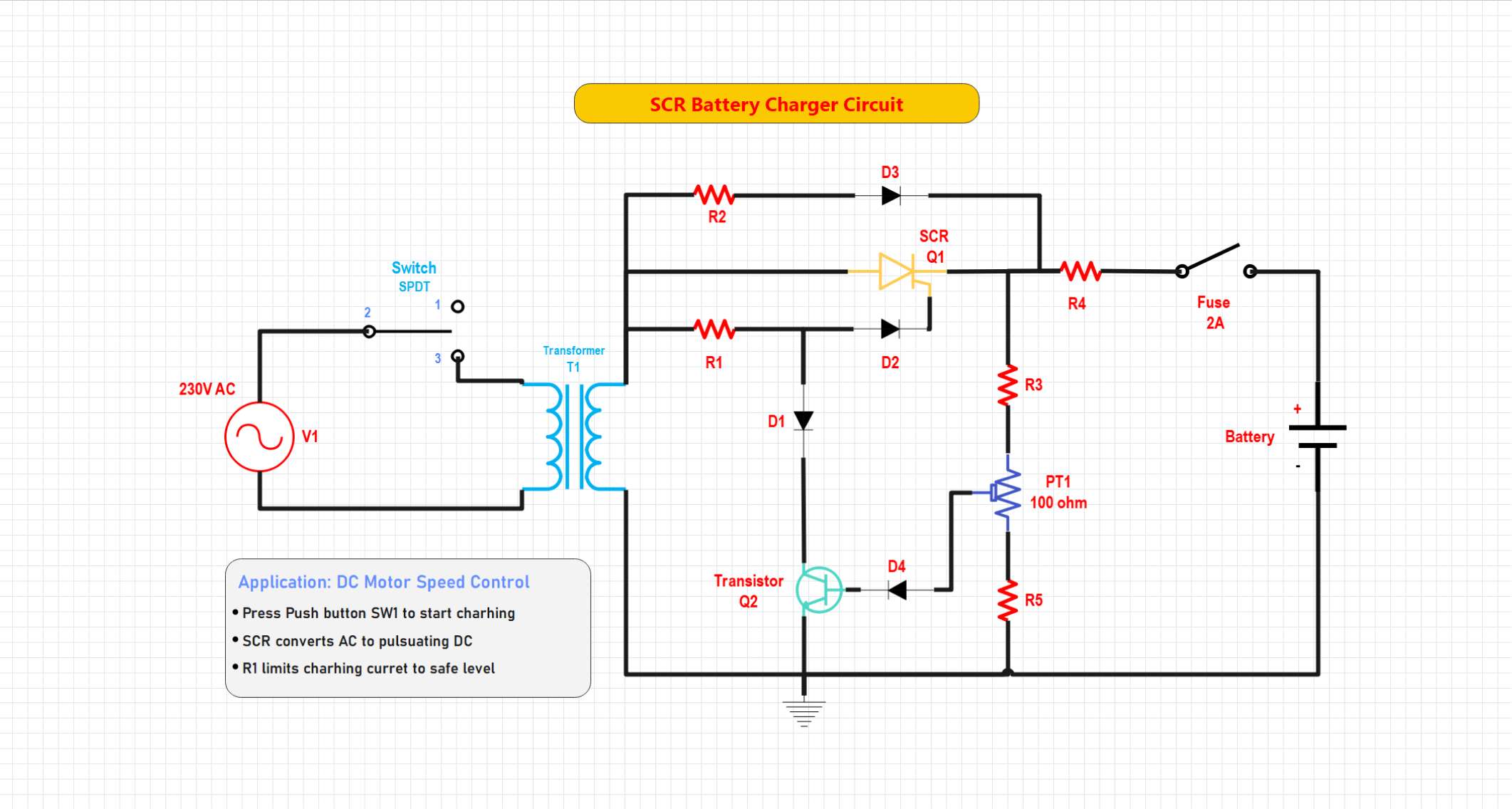
Example 2: SCR Battery Charger Circuit
This circuit incorporates the use of an SCR to control the current of DC charging used to power a battery. A control signal to the SCR depends on the battery voltage and turns it off. The trigger circuit has the capability of having a stop or delay mode activated when battery voltage is raised to a set value to prevent overcharging. The design can be easily charged using the battery, and the heat about the battery is minimized to extend the battery run time using its auto-controlled current flow.
This circuit demonstrates an SCR-based battery charger that converts AC to controlled DC for charging a battery. A transistor sensing network adjusts the SCR's conduction angle based on the battery voltage, automatically reducing the charging current when full charge is reached. The design includes a fuse and current-limiting resistors for protection, providing an efficient and safe automatic battery charging system.
How to Draw an SCR Power Control Circuit Diagram in EdrawMax
Designing an SCR-based power control circuit is simple with EdrawMax. The software enables users to create accurate dimmer and motor control diagrams through its drag-and-drop interface, which includes pre-built components for SCRs, DIACs, and resistors and capacitors. You can design and export a professional schematic in just minutes.
Step1 Make a New Project
Open EdrawMax. Click New on the left panel.
Select Blank Drawing to begin with a blank canvas.

Step2 Select Electronic Symbol Libraries.
Select the left toolbar of Symbols or More Symbols. Right-click Manage and then Add More Symbols.
Add the Electrical or Circuit and Logic libraries to use such components as MOSFETs, diodes, inductors, and capacitors.

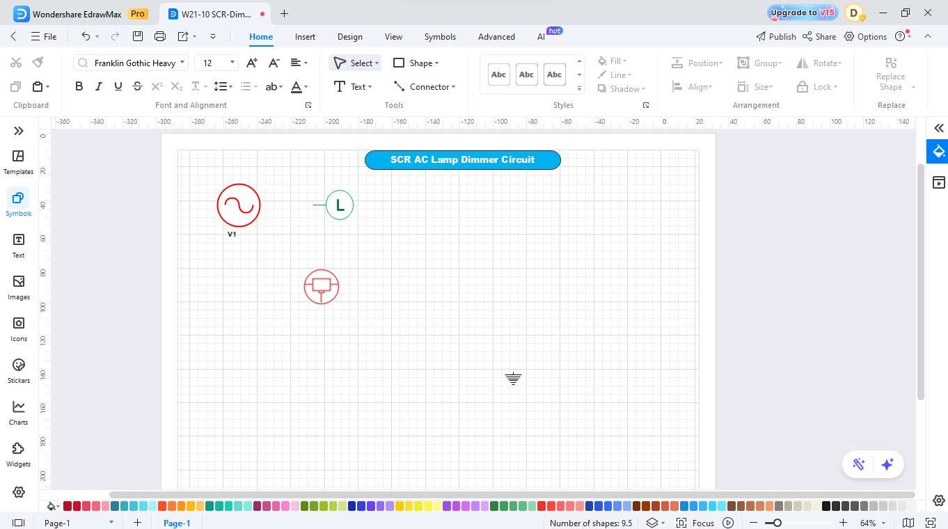
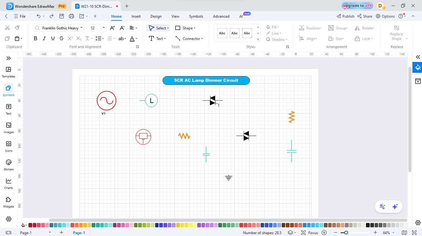
Step3 Add the AC Source, Lamp, and Inductor.
- Add an alternating current (AC) source.
- Now, drag a Lamp and a Potentiometer for controlling voltage.
Step4 Include the Resistors, Capacitors, and DIAC
- Symbolically place capacitors in your circuit.
- Insert a DIAC and a resistor for controlling the current through the circuit.
- Be sure to add the ground as well to complete the circuit.
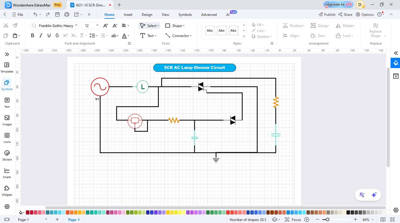
Step5 Complete the Wiring
- Ensure the components are placed correctly for proper connection.
- Use the connector tool to join the components and thus complete the wiring.
Step6 Label the Components and Write Descriptions
- Name the parts (e.g., DIAC, AC source, lamp).
- Write the descriptions for better understanding.
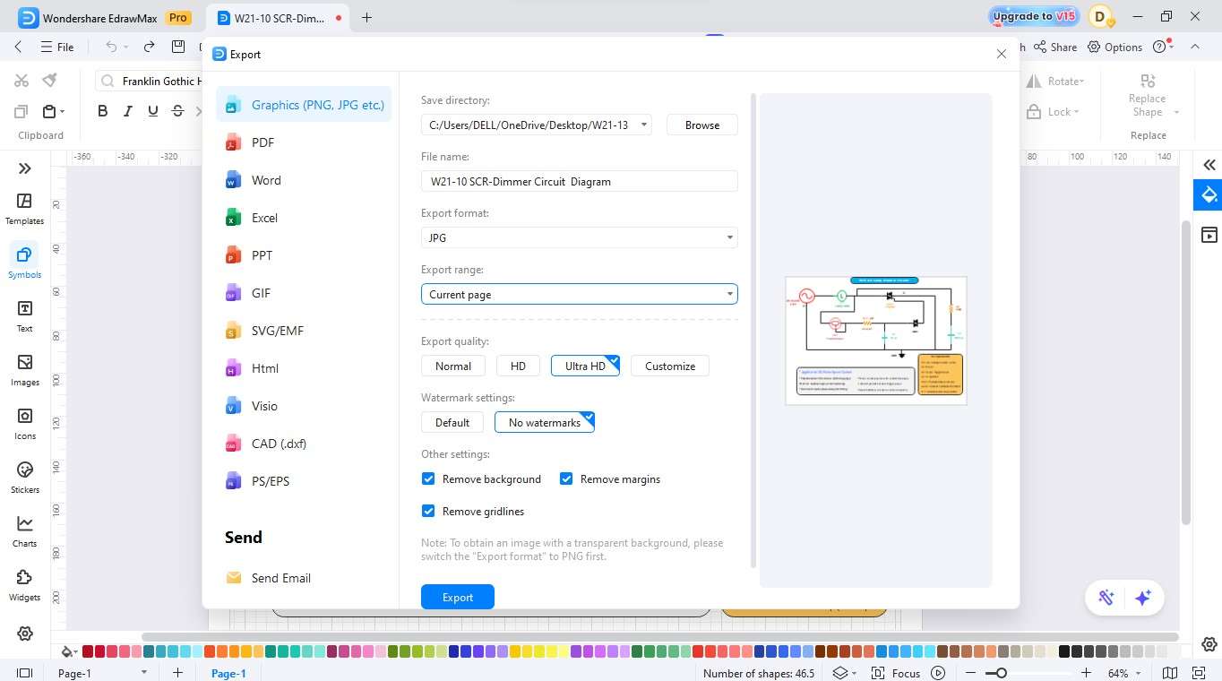
Step7 Export
- Finalise the diagram by checking the alignment and spacing to ensure it is clear.
- After that, save your design.
- Then export your diagram through various export options, which include PDF, PNG, and SVG formats.
Create a Circuit Diagram Online Now
EdrawMax is a comprehensive diagramming tool that helps you quickly and easily design SCR power control circuits. The software features a user-friendly drag-and-drop interface, which enables users to create professional circuit diagrams through its complete library of electrical symbols, including SCRs, DIACs, resistors, capacitors, and potentiometers. The software lets users generate and distribute exact schematics by using drawing and formatting tools, which complete tasks within less than ten minutes.
Key Features
- The system contains a wide range of circuit symbols, which include SCRs, DIACs, resistors, capacitors, and additional components.
- The application provides users with a simple drag-and-drop interface that lets them build circuits automatically through its connection management system.
- The platform enables real-time collaboration because of its protected cloud storage system, which simplifies team operations.
- The software enables users to access pre-designed circuit templates, which they can customize for faster circuit development.
- The application enables users to save their diagrams through various export options, which include PDF, PNG, and SVG formats.
Best Practices for Creating Accurate Designs
A correctly designed SCR circuit enables stable operation and efficient power regulation, which helps to extend the lifespan of its components. The prevention of faults, power losses, and overheating becomes possible through proper attention to component ratings, heat control, and protection measures.
Follow these key tips for reliable design:
Use Properly Rated SCRs and Components
Choose an SCR that fulfils both voltage and current requirements for your application. The triggering network requires resistors, capacitors, and DIACs, which must have ratings that match the operating voltage.
Control Heat Dissipation
SCRs generate heat during conduction. Mount them on proper heat sinks or metal surfaces to prevent thermal damage and maintain consistent performance.
Add Surge and Noise Protection
The system requires snubber networks or RC filters to protect against voltage spikes, which will help prevent false triggering. The system protects vital equipment while maintaining exact power management control.
Conclusion
An SCR power control circuit diagram serves as an excellent reference for understanding and designing efficient lamp dimmers or battery chargers. The circuit shows how SCRs, DIACs, resistors, and capacitors function together to achieve proper voltage and current control. The drag-and-drop interface of EdrawMax enables users to build professional SCR circuit diagrams through its extensive symbol collection, which provides quick and simple design capabilities for users of all skill levels.
AI Diagram Generator
Enter your prompt. Upload files if needed. Generate diagrams, charts, or slides instantly.


